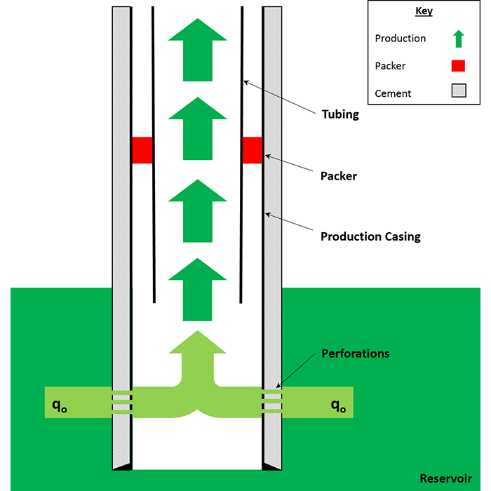
An example of a Cased and Perforated (“Cased and Perf’ed”) Completion across a single-layer reservoir is shown in Figure 7.12.
The advantages of a cased and perforated completion in the well (Figure 7.12) include:
- in single-layer reservoirs, a cased and perforated completion is a simple, durable completion;
- for multiple-layer reservoirs, a cased and perforated completion allows for zonal isolation for different zones;
- for multiple-layer reservoirs, a cased and perforated completion allows selective stimulation (different stimulation treatments for different reservoir zones);
- very flexible with many possible cased and perforated completions available for the same problems.
The disadvantages of a cased and perforated completion in the well (Figure 7.12) include:
- the costs of the perforating thick reservoir zones may be excessive;
- well logs for future reservoir evaluation, workover planning, or determination to Plug and Abandon the well are limited to Cased Hole Logs (subset of well logs that are not impacted or are designed not to be impacted by the presence of the casing);
- deepening of the well is more difficult than in open-hole completions.
As alluded to throughout the lesson, casing is high quality steel pipe that is major structural part of the oil or gas wells. Off the shelf, the casing has no openings and, consequently, requires Perforation to gain access to the reservoir. There are many grades and specifications for the casing steel quality. The objectives of the casing are:
- provide wellbore stability;
- protect natural aquifers from work fluids and produced fluids;
- control well pressures during drilling, production, and workovers;
- aid in zonal isolation in cased and perforated well completions.
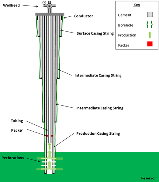
All modern wells use strings of multiple casing. The casing strings that can be used in the oil and gas wells include:
- conductor casing
- surface casing
- intermediate casing
- production casing
- liner
- liner tie-back casing
Several of these casing strings are shown in Figure 7.13. We will discuss the different casing strings and their roles in drilling the well in Lesson 8 when we discuss drilling operations. In our current discussion on cased and perforated completions, however, we are referring to the production casing. The role of the production casing is to:
- aid in zonal isolation;
- protect the wellbore and the outer casing strings from reservoir pressures;
- protect the well and environment in case of a tubing leak.
Cased and perforated wells are completed by first drilling through the reservoir (or sometimes a little deeper than the bottom of the reservoir). The production casing is then run and cemented in-place. Next, the tubing string is run, and all packers are set. Finally, the perforation guns are run and fired to create the access to the reservoir.
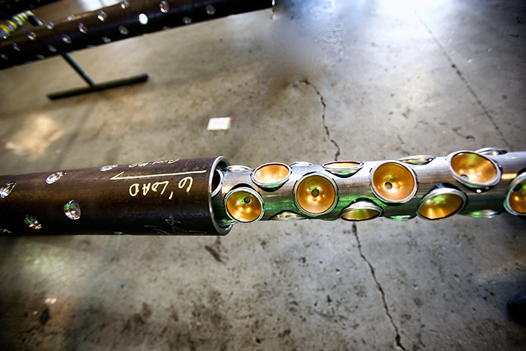
A perforation gun is an array of shaped charges that can be arranged in many configurations to achieve the objectives of the well. The perforation guns can be conveyed (deployed) either on wireline (wireline conveyed perforation guns) or on the tubing itself (Tubing Conveyed Perforation, TCP, guns). Figure 7.14 shows a typical TCP gun.
Cased and perforated completions provide the highest level of control for the well, and when used in conjunction of systems of Packers and Bridge Plugs, are capable of providing Zonal Isolation across multiple reservoir zones.
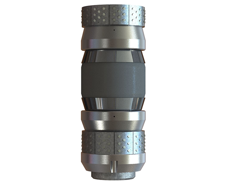
We have already discussed packers earlier in the lesson (see Figure 7.08). As I stated, packers provide isolation in the annulus of the well. On the other hand, bridge plugs provide isolation inside the tubing of the well. Figure 7.15 shows a picture of a bridge plug. The bridge plug can either be conveyed on a wireline or with a workover string. The sealing element of the bridge plug is then set inside the tubing to create the isolation. A bridge plug can be either retrievable or permanent.
We are now in a position to discuss the role of well completions and Zonal Isolation. I think many of the concepts on zonal isolation that we discussed earlier in the lesson will become much clearer starting from this point.
In our earlier examples, Figure 7.07 through Figure 7.12, we considered a reservoir with a single layer or zone. Now, let’s consider a reservoir with two reservoir zones with the possibility of producing unwanted fluids from one or both of the zones as shown in Figure 7.05 and Figure 7.06.
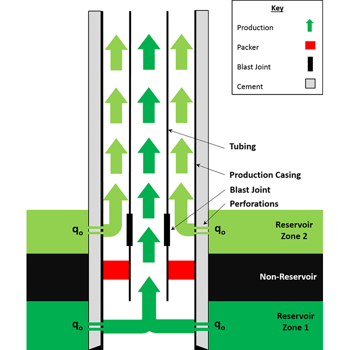
If we know that water will be produced from the lower reservoir interval (a common problem based on the density of water compared to that of gas or oil), then we may consider a well completion such as that shown in Figure 7.16. This completion is a common completion when we are certain that water will enter the well in the lowermost zone.
In Figure 7-16 (A), the well is initially completed with no bridge plug installed. The Blast Joint shown in this figure is a thicker walled / stronger section of tubing that is placed across all perforations in multiple zone completions to protect the production tubing string from erosion due to the jetting action of produced fluids through the perforations. In the configuration shown in Figure 7.16 (A), oil production is allowed from both reservoir zones with the fluids from the lower zone, Reservoir Zone 1, being produced through the tubing and fluids from higher zone, Reservoir Zone 2, being produced through the Annulus (space between the tubing and casing).
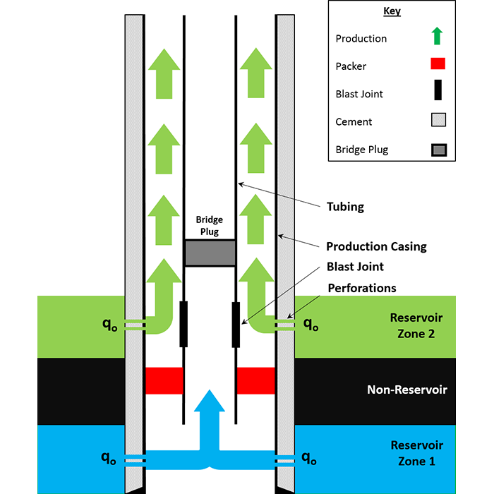
At some later date, water production occurs from the lower reservoir zone, Reservoir Zone 1, from one of the water sources shown in Figure 7.5. When this water production becomes too excessive, a bridge plug can be run through the tubing on wireline and seated at the appropriate depth as in Figure 7.16 (B). This is what we refer to as zonal isolation which we use to isolate production of unwanted fluids.
The action of running and seating the bridge plug at a date after production has begun is referred to as a Well Intervention or a Workover. In the case of this example, this is specifically referred to as a Water Shut-Off Workover. Since we are able to the run the bridge plug on a wireline through the tubing (not requiring a drilling rig), we can also refer to this as a Wireline Workover or a Through-Tubing Workover.
For the well’s initial completion Figure 7.16 (A), water production from the lower intervals (as opposed to water production from higher layers – see Figure 7.05) may be assessed prior to drilling the well by the behavior of Offset (neighboring) wells or with open-hole logs and Drill Stem Tests (DSTs) after drilling the well. If the well is in an exploratory geologic basin or new field or reservoir, then you need to incorporate flexibility into completion designs of the early wells.
The advantages of this completion (Figure 7.16) are:
- produce oil at high rates due to flow through both the tubing and annulus resulting in faster payout for the well and the possibility of improved long-term economics;
- provide the ability to selectively isolate (shut-off) the bottom zone, Reservoir Zone 1, with a relatively inexpensive wireline workover.
The disadvantages of this completion (Figure 7.16) are:
- the upper zone cannot be produced through the tubing;
- only the zone serviced by the tubing can be isolated with a relatively inexpensive bridge plug;
- working over the upper zone requires the temporary shut-in of both zones;
- the casing is subjected to higher pressures (the pressure of Reservoir Layer 2), corrosion, and erosion from production;
- the potential for tubing leaks to develop if a differential pressure exists due to differential reservoir pressures;
- only the lower zone (the zone being produced through the tubing) can be assisted with artificial lift;
- sand production from the upper zone may create sand-fill in the annulus and cause stuck pipe if the tubing is attempted to be pulled (a Tubing Change-Out Workover).
To help illustrate the flexibility of the cased and perforated completion, if water is known to be produced from the upper layer, Reservoir Zone 2, then there are tools available (cross-over valve/choke) which can be used to change the flow paths for the produced fluids. That is, at the time of implementing the original completion, if it is suspected that water production may come from the upper zone, then a cross-over valve can be installed to have the fluids from the lower interval, Reservoir Zone 1, enter the well as in this figure but cross-over to the annulus up-hole, while the fluids from the higher interval enter the well as seen in the figure but cross-over to the tubing. In this case, we would be able to isolate the upper zone (now produced through the tubing) with a bridge plug, but not the lower zone (now produced through the annulus).
Again, to further illustrate the flexibility of the cased hole and perforated completion, we can discuss another well completion for this well. From the list of disadvantages for this completion, we see that we are subjecting the casing to high levels of well stress (high pressures, possible corrosion, and possible erosion). If a critical objective of the well is to protect the casing from these well stresses, then the well completion shown in Figure 7.17 may be considered.
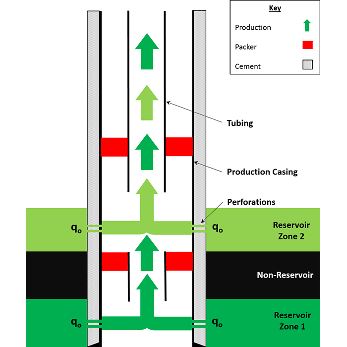
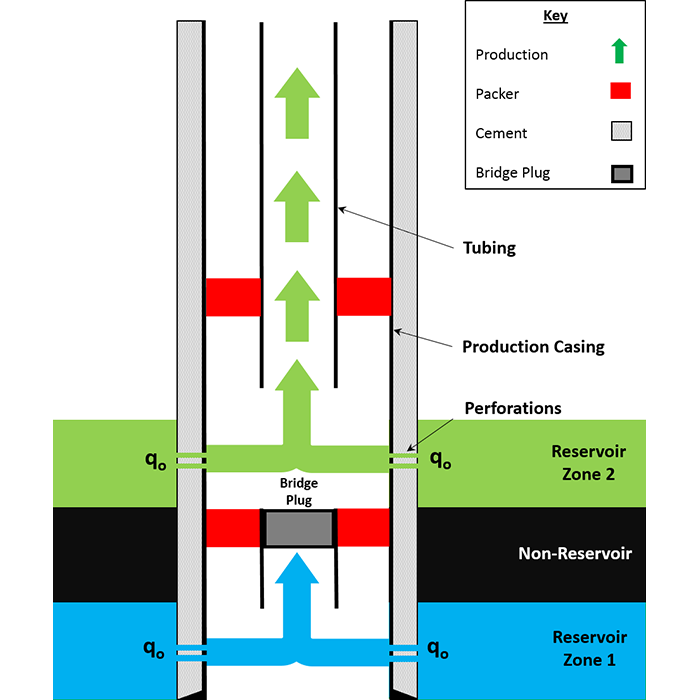
This example shows the same two-zone reservoir as in the earlier example (Figure 7.16). In this completion, we have used a Packer – Tail-Pipe Assembly to provide zonal isolation of the water prone, lower layer. This completion, however, results in commingled (mixed) production from the two layers in the tubing. Commingled production may result in production problems if the fluid chemistries in the produced fluids are incompatible. Wax or asphaltene deposition may occur from the two oils if they are significantly different, while scale deposition from produced waters may occur it the chemistries (dissolved solids) of the produced waters are significantly different.
The advantages of this completion (Figure 7.17) are:
- there is no annular flow, so there are no issues with high pressures, corrosion, or erosion acting on the casing;
- the pressure gradient in the annulus and tubing are approximately equal which protects the tubing from tubing leaks.
The disadvantages of this completion (Figure 7.17) are:
- lower production rates – both reservoir zones are being produced through a single tubing string. The smaller cross-sectional area for flow creates a larger pressure drop in the tubing and restricts the total production from the well;
- production from the two reservoir zones is commingled;
- only the lower zone can be isolated with a relatively inexpensive bridge plug.
We can design a third completion for this well and two-zone reservoir which addresses some of the disadvantages of the packer – tail pipe assembly. This type of completion is referred to as a dual-string completion and is shown in Figure 7.18.
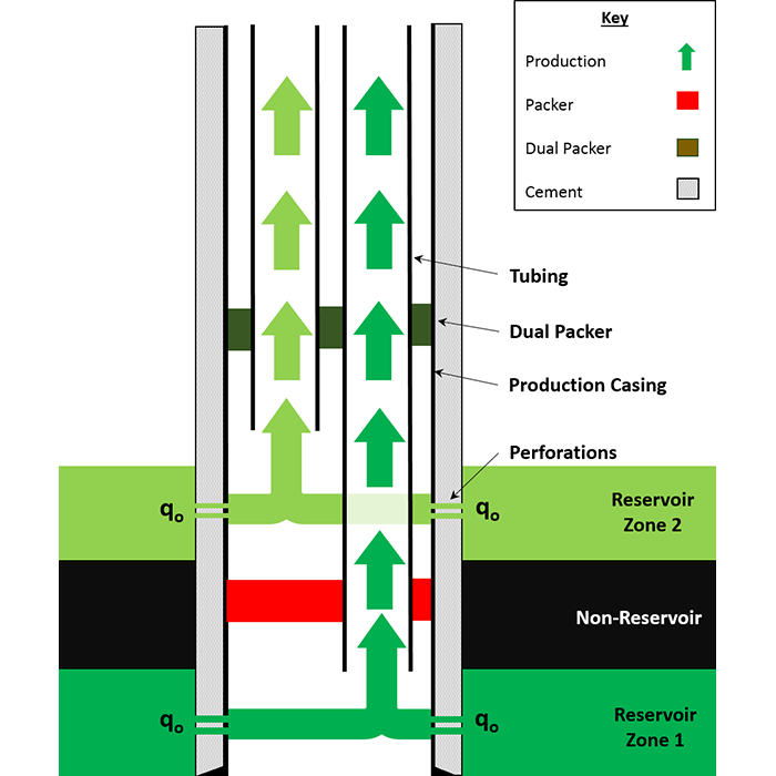
In Figure 7.18, we have completed the well with two tubing strings. The key to this completion is the dual-packer. This type of completion can only be run if the original wellbore and production casing have sufficient Inner Diameters to support this equipment and the tools required to run this equipment. This issue is typically considered during the design and planning stage of the well, and if a dual-string completion is to be used in the well, then a larger diameter well can be drilled.
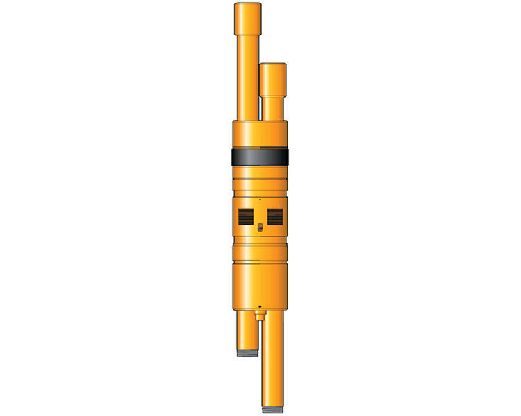
A detailed schematic of a dual packer is shown in Figure 7.19.
The advantages of this completion (Figure 7.19) are:
- there is no annular flow, so there are no issues with high pressures, corrosion, or erosion acting on the casing;
- the pressure gradient in the annulus and tubing are approximately equal which protects the tubing from tubing leaks;
- wireline workovers practical for both reservoir zones;
- production from the two reservoir zones is not commingled;
- both zones can be isolated with a relatively inexpensive bridge plug.
The disadvantages of this completion (Figure 7.19) are:
- expensive completion (two tubing strings);
- the dual string completion is a complex well completion;
- these completions can only be run if the wellbore and production casing have sufficiently large inner diameters;
- lower production rates – production rates are lower because the cross-section to flow is further reduced;
- logging the well may be problematic as logging tools must be available for the restricted dimensions in these completions.
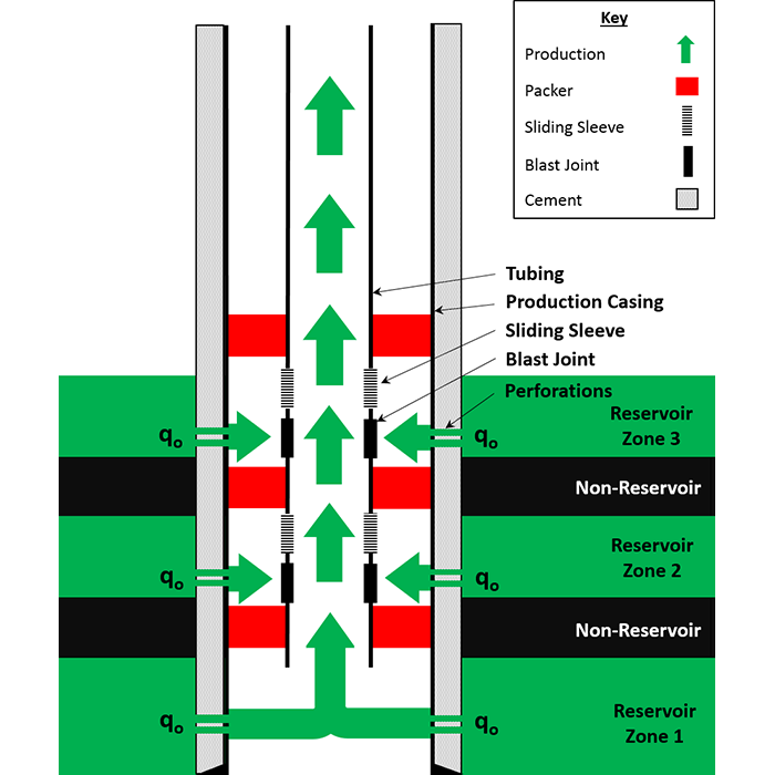
To this point, we have limited our discussion to two-zone reservoirs. I will provide one last example of multi-zone well completion using Sliding Sleeves. This multi-zone completion can also be used for the two-zone reservoir example that we have been discussing. A sliding sleeve completion for a multiple zone reservoir is shown in Figure 7.20.
A sliding sleeve is a device that is run as part of the tubing string that can be shifted to an open position to allow communication between the tubing and annulus or shifted into a closed position to prevent tubing-annuls communication. The sliding sleeve can be shifted to the open or closed position multiple times using wireline or coiled tubing. In this completion, the lowest reservoir zone can be isolated with a bridge plug.
The advantages of this completion (Figure 7.20) are:
- there is no annular flow, so there are no issues with high pressures, corrosion, or erosion acting on the casing;
- the pressure gradient in the annulus and tubing are approximately equal which protects the tubing from tubing leaks (the sliding sleeves themselves may leak);
- all zones can be isolated with a relatively inexpensive wireline or coiled tubing workover.
The disadvantages of this completion (Figure 7.20) are:
- high costs for multiple sliding sleeves and packers;
- lower production rates – production from all reservoirs zones flow through a common tubing string;
- the sliding sleeve completion is a very complex well completion (sliding sleeves and packers susceptible to failure);
- difficulty in monitoring performance of individual reservoir zones.
In the bullet list of overriding Well Design Considerations, we listed simplicity as one of the overarching goals for the well completion. As we have seen in these examples, there may be number of completions that can be used to achieve the specific objectives of the well: sand control, unwanted fluid control, etc. As we have also seen, these well completions can get very complex. One measure of the complexity of the completion is by the number of packers that are required by the completion. Remember, any piece of equipment put into a well; a packer, a bridge plug, a sliding sleeve; can fail. By keeping the completion design simple we are reducing the possibility of the entire completion failing based on the failure of one key component.
We are always trying to make our completions as simple as possible with the ability to achieve the completion objectives: sand control, water control, gas control, amongst others. When we design the completion, we can try to reduce the complexity of the completion by grouping layers in the reservoir. If several adjacent reservoir layers act in unison, then we can reduce the complexity of the completion by grouping the layers as if they were a single layer.