Another aspect of well design is the application of artificial lift. When no artificial lift is applied, we refer to the well as a Natural Lift Well or a Naturally Flowing Well (i.e., the higher reservoir pressure is capable of lifting the heavy liquids without any assistance). As the reservoir pressure depletes due to production or the density of the fluid column in the well increases due to increasing water production rates, then artificial lift may be required to produce the wells at economic rates.
Artificial lift refers to the application of pumps or gas injection to assist the lifting of the heavier reservoir liquids. These methods may be applied early in the life of the field or reservoir to enhance the economics of marginal wells or later in the life of the field or reservoir as subsurface conditions change. In addition to increasing the production rates of wells, due to the reduction in the flowing bottom hole pressures of wells, from Material Balance Considerations, artificial lift can also increase the total recovery from the reservoir.
There are several methods of artificial lift including:
- beam pumps (Nodding Donkey, Sucker Rod Pump)
- electrical submersible pumps (ESPs)
- hydraulic pumps
- progressive cavity pumps (PCP pump)
- gas lift
We will only discuss two methods of artificial: ESPs and gas lift. The design of ESPs and gas lift systems can also be considered in the IPR-TPC analysis. To perform the analyses, a segmented well hydraulics model (discussed in Lesson 6) must be designed to generate the appropriate tubing performance curves for use in the analysis. This is done by adding Downhole Devices into our well model. A downhole device is a piece of oilfield equipment with known rate pressure-rate behavior. Current generation well hydraulics software has options for all common downhole devices including (but not limited to) downhole pumps, gas lift valves, chokes, sub-surface safety valves (SSSV), gravel packs, perforations, etc.
A well completion with a downhole ESP device is shown in Figure 7.24. There are two ways to generate the tubing performance curves for ESP wells/completions:
- the horsepower conversion method
- Pump Curve method (a pump curve is a series of curves including the pump head (pressure boost) versus capacity (flow rate), power input (horse power) versus capacity, and pump efficiency versus capacity – all plotted on the same graph). The pump curve method requires that the user supply a pump curve for a specific pump to the model and the software iteratively determines the pressure boost and temperature change for the prevailing well conditions. This method is more accurate than the horsepower conversion method because the pump efficiency is a function of the capacity but is iterative.
I am including the links to a PetroWiki article and a Schlumberger Oilfield Review article on Electric Submersible Pumps.
- PetroWiki [5]: Electrical Submersible Pumps
- Schlumberger Oilfield Review: Defining Electrical Submersible Pumps [6]
The Schlumberger Oilfield Review link (second link) provides a simple schematic of an ESP (Figure 1 in the article) and an example of a pump curve (Figure 2 in the article).
The horsepower conversion method is a simple method to implement because it is non-iterative, so we will continue our discussion using this method. In this method, the pressure boost through the pump (difference between the outlet and inlet pressures) and the temperature change of a fluid going through the pump are defined by:
and
Where:
- 942.86 and 0.185 are equation constants
- is the pressure boost from the pump, psi
- is the temperature increase through the pump, ºF
- is power rating of the pump (power is the rate of work, +W, in Figure 7.24), horsepower
- is the density of the well fluids (mixture), lbm/ft3
- is the pump efficiency (assumed constant in the horsepower conversion method), dimensionless
- is the total production rate of the well fluids (mixture) at the pump height, bbl/day
- is the specific heat of the fluid, BTU/(lbm-ºF)
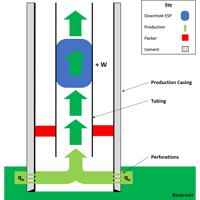
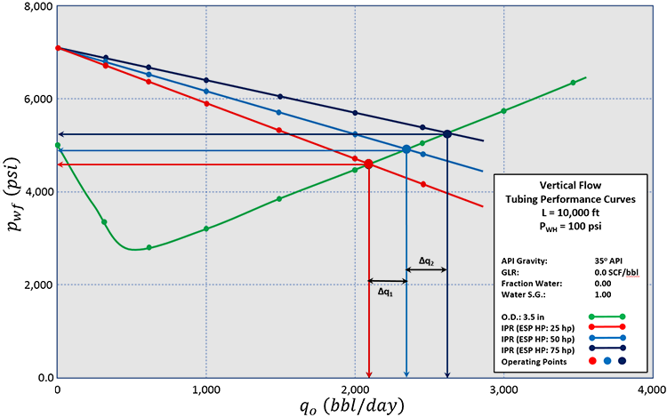
Figure 7.25 shows a typical Inflow Performance Relationship – Tubing Performance Curve for ESP Optimization and Design. Typically, when optimizing ESPs, we evaluate:
- the size of the pump (horsepower rating)
- the number of pump stages
- the depth of the pump
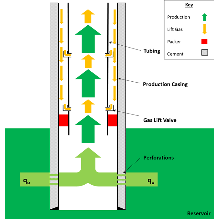
Gas lift is an artificial lift method in which we install Gas Lift Valves in the tubing to inject gas into the flowing well stream. The lift gas injected is injected down the annulus and enters the tubing through the gas lift valves. The objective of introducing the external gas into the well stream is to lighten the well column.
I am including the link to the PetroWiki [5] article on Gas Lift:
- PetroWiki: Gas Lift
This article contains more details on gas lift than I am covering in the course lessons including discussions on two variants of gas lift: continuous gas lift and intermittent gas lift.
A typical completion with gas lift valves is shown in Figure 7.26. The gas lift device in a well hydraulics model would simply be the gas lift injection rate of the valve against the backpressure of the produced fluids. The Inflow Performance Relationship – Tubing Performance Curve for Gas Lift Optimization and Design looks like the one illustrated in Figure 7.25. When optimizing the gas lift design, the parameters that are typically investigated include:
- the gas lift rate
- the placement of the gas lift valves (particularly the bottom valve)
[5] Society of Petroleum Engineers technology website: PetroWiki
[6] Rick, von Flatern: “Electrical Submersible Pumps,” Oilfield Review, Schlumberger (2015)