The hoisting system on a drilling rig does the heavy lifting on the rig. It is used to raise, lower, and suspend the drill string and lift casing and tubing for installation into the well.
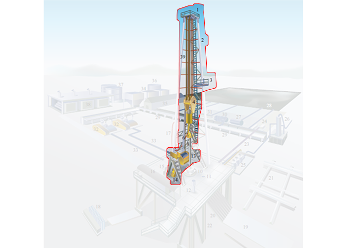
In the detailed rig schematic (Figure 9.02b) the hoisting system is comprised of:
- the Crown Block (Item 1)
- the Mast/Derrick (Item 2)
- the Monkey Board (Item 3)
- the Traveling Block (Item 4)
- the Hook (Item 5)
- the Swivel (Item 6)
- the Drawworks (Item 13)
- the Weight Indicator (Item 14)
- the Drilling Line (Item 39)
A schematic of the hoisting system is shown in Figure 9.03 for a kelly drive rig. In this figure, the derrick (or mast) provides the structural support for the hoist system. It must be capable of supporting the entire load on the system including the weight of the drill string (accounting for buoyancy effects) and any frictional forces.
The crown block and the traveling block form a Block and Tackle System on the rig. The drill line can be strung as pairs of 2 through 12 lines (six pairs). The greater the number of lines (and pulleys) in the block and tackle system, the greater its lifting power but at the expense of slower upward and downward movement of the system.
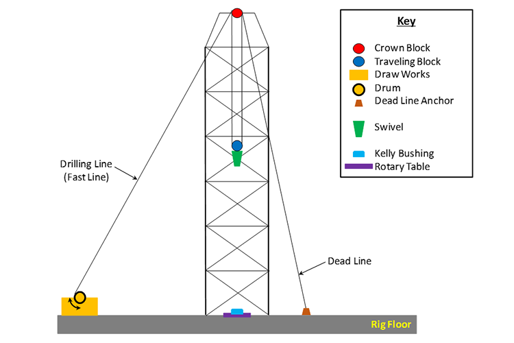
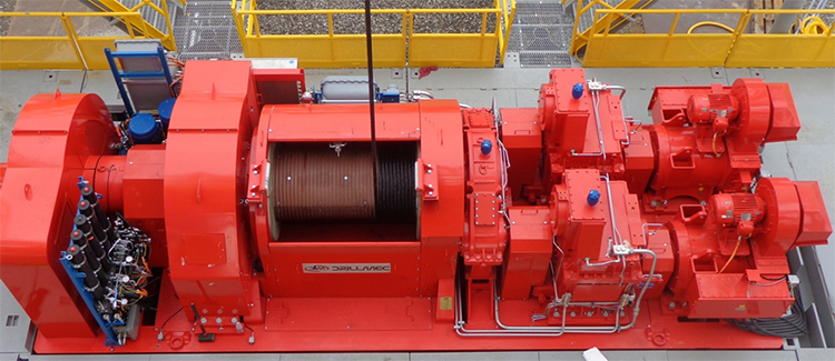
The drawworks of the hoisting system is a winch that reels the drilling line in or out causing the traveling block to move up or down. The drawworks is the component of the hoisting system that consumes energy from the power system. The drum on the drawworks is grooved to accommodate a specific size drilling line. Figure 9.04 shows a photo of an actual drawworks used on a drilling rig .
Not shown on the schematic or the photo is the braking system on the drawworks. Modern rigs use both a mechanical brake and an electromagnetic brake. The braking system is an integral part of the drilling process because it is used to control the Weight-on-Bit (WOB) during drilling. The two most important drilling parameters within the Driller‘s control to maximize the Rate of Penetration (ROP) are the weight-on-bit and the rotational speed of the rotary system in Revolutions per Minute (RPM).
The weight-on-bit is achieved with the weight of the drill pipe and Drill Collars, however the optimum weight-on-bit is often less than the total weight of the drill string. The brake is used to take up some of the weight of the drill string, so that the weight-on-bit is only a fraction of the total weight.
Also shown in Figure 9.03 is the Swivel. The swivel is the link that connects the hoisting system to the rotary system and to the circulation system. The function of the swivel is to:
- hold the weight of the drill string on the hoisting system (the hoisting system does not rotate);
- allow rotation of the drill string below it (the drill string, Bottom-Hole Assembly (BHA), and drill bit all rotate);
- allow passage of the drilling fluid from the circulation system (non-rotating) to the drill string, Bottom-Hole Assembly (BHA), and drill bit of the rotary system.