We have discussed the components of the drilling rig, now let’s discuss the drilling process itself. An oil or gas well is drilled in a very ordered sequence. The steps in this sequence are almost universally applied to the drilling of all wells.
- Plan the Well: As we have discussed, exploration well prospects are generated by exploration geologists; while development wells locations and objectives are generated by development geologists. Once the surface locations and well objectives are known, the geologists work with the drilling engineers to develop the detail drilling proposals. In addition, all permits (environmental, safety, regulatory, etc.) are acquired during the final stages of the planning process when a solid well proposal is developed.
- Perform Shallow Gas Survey: To ensure there are no shallow gas hazards which may result in a kick or blow out, a shallow gas survey is performed to identify the locations and depths of any potential shallow gas hazards. Preliminary surface locations and well trajectories may be altered from the original well proposal to avoid these shallow gas hazards.
- Prepare the Wellsite: The site preparation involves building clearing land for use by the rig, building access roads to the well site or well pad, construct infrastructure for water, water disposal, and electricity, dig and line all mud pits to prevent ground water or water table contamination, dig reserve pits for cutting storage (for eventual disposal), and drill the holes which will eventually become the rat hole and the mousehole. The site preparation may involve multiple contractors and companies to perform all of the required work. As we discussed in earlier lessons, a lot of site-preparation time and the environmental footprint can be minimized if multi-well pads are used in the field development.
- Set the Conductor Casing: Prior to the arrival of the drilling rig, an Auger Unit (in hard rock regions) will drill a large diameter hole capable of accommodating 18 in. to 36 in. conductor casing (see Figure 9.16). In soft rock regions or at offshore locations, a diesel hammer may be used to hammer the conductor casing into place. The conduct casing may go to depths of 40 to 300 ft depending on the location. The conductor casing is typically set through the top soil and loose rocks to the bed rock. The objective of the conductor casing is to isolate the wellbore from the top soil to ensure that loose debris does not enter the well during early drilling operations. The conductor casing is then cemented into place.
- Move-In and Rig Up (MIRU): Once the wellsite is prepared and the conductor casing is in-place, the rig is brought on location. Most land rigs, particularly those in North America, are transported on multiple trucks. Once on the well site or well pad, the rigging-up process begins. Rigging up the well consists of taking the rig modules from the trucks and assembling the rig. Included in the rigging up process is setting-up all of the rig systems and testing these systems. Here is a YouTube video, "Rigging up Land Drilling Rig" (3:35), showing the Rigging Up process of the derrick:
Pioneer Drilling 60 Series Rig-up Animation | Drilling Animation | Land Rig Animation | Oil & Gas. This video contains only background music with no words.Source: Industrial3D Inc | I3D.
Transporting and assembling the rig may take 50-75 workers (two crews), 35 – 40 vehicles, and take up to four days. If a multi-well pad is used, once the rig is rigged-up for the first well, then the rig can simply be skidded over to the next location without having to dig-down. - Spud the Well: After the rig has been inspected and all of the systems tested the well can be Spudded. Spudding a Well refers to starting the rotary drilling operations for that well.
- Drill Down to the Surface Casing Depth: The first section of the well to be drilled is the section that goes down to the pre-determined surface casing depth (Casing Point). Obviously, for this section of the wellbore, the drill bit diameter must be smaller than the ID (inner diameter) of the conductor casing. In this shallow section of the wellbore, fresh water aquifers (both for personal and municipal use) exist. As discussed earlier, shallow gas hazards may also exit. The objectives of drilling this first section of the well is to allow the setting and cementing of the surface casing to:
- protect the fresh water aquifers by placing a steel and concrete barrier to isolate the water table from the well;
- protect the well from the aquifer (cutting of the drilling fluids with fresh water);
- protect the well from shallow gas hazards.
- Run and Cement the Surface Casing: Once the surface casing point is reached, the surface casing is run into the wellbore and cemented into place. This process is performed by:
- Pulling Out of Hole (POOH): Tripping out of the hole with the drill pipe to remove it from the wellbore during cementing operations;
- running the surface casing;
- pumping a cement slurry down the interior of the casing;
- chasing the cement with drilling fluid to displace the cement up into the annular space between the casing string and the wellbore (rock);
- allowing time for the cement to Cure (harden).
The BOP is then installed on the surface casing string. - Continue this Process to Drill to the Next Casing Point: This drilling process is continued to the next pre-determined casing point. The selection of these intermediate-string casing points is beyond the scope of the class, but the criteria are based on the mud weight, the Fracture Pressure of the formations to be drilled (the pressure that causes the formation to fracture), the locations of any Lost Circulation Zones, and the locations of any High Pressure Zones. As we discussed earlier, any of these situations may result in a kick and a potential blowout. The objectives of the intermediate casing strings are:
- isolate unstable hole sections behind pipe;
- isolate lost circulation zones behind pipe;
- isolate under-pressured zones behind pipe (prevent lost circulation);
- isolate over-pressured zones behind pipe (prevent a kick);
- isolate multiple producing zones
- Continue this Process to Drill to each Casing Point: This process is repeated for each of the planned casing points. Obviously, as successive casing strings are run and cemented into place, smaller diameter tools and drill bits must be used for continued drilling operations. As we discussed earlier, the two most important drilling parameters within the Driller’s control to maximize the Rate of Penetration (ROP) of the drill bit are the weight-on-bit and the rotational speed of the rotary system in Revolutions per Minute (RPM).
- Continue this Process to Drill to Total Depth (TD): Once the final intermediate casing string is run and cemented, the drilling process is continued until the well reaches the TD (Total Depth) of the well. At this point, the well is said to be TD’ed.
- Log the Well with Open-Hole Logs: At this point, the sand face is exposed to the well and Open-Hole Logging Tools can be run in the well. Open-hole logs are used to measure certain properties of the subsurface formation that are of interest to the geologists and engineers working on the well and the reservoir.
- Run and Cement the Production Casing String or Liner: If a production casing string or production liner is to be used in the completion, then they are run and cemented at this time.
- Compete the Well: Install the well completion as discussed in earlier lessons:
- tubing
- gravel packs
- packers
- sliding sleeves
- stimulation
- acidize the well
- hydraulically fracture the well
- artificial lift
- Rig Down and Move Out
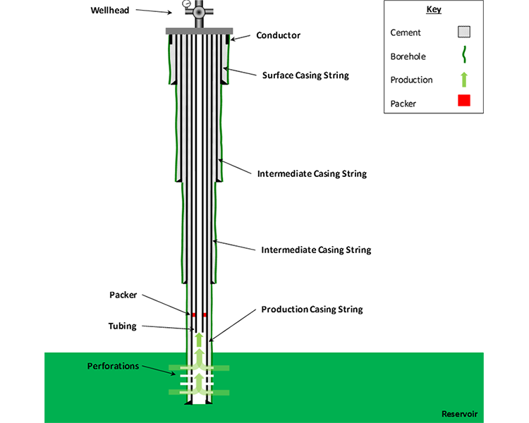
Figure 9.16: Typical Hydrocarbon Production Well with Multiple Casing Strings including two Intermediate Casing Strings
Source: Greg King © Penn State, licensed CC BY-NC-SA 4.0
Finally, here is a YouTube video, "Drilling Animation" (5:58), showing the entire drilling process. This animation is from Chesapeake Energy, and it discusses the drilling process for a Marcellus Shale well: