The circulation system on the rig is the system that allows for circulation of the Drilling Fluid or Mud down through the hollow drill string and up through the annular space between the drill string and wellbore. It is a continuous system of pumps, distribution lines, storage tanks, storage pits, and cleansing units that allows the drilling fluid to fulfill its primary objectives (these will be discussed later in this lesson). The mud pumps of the circulation system and the drawworks of the hoisting systems are the two largest draws on the power from the power system
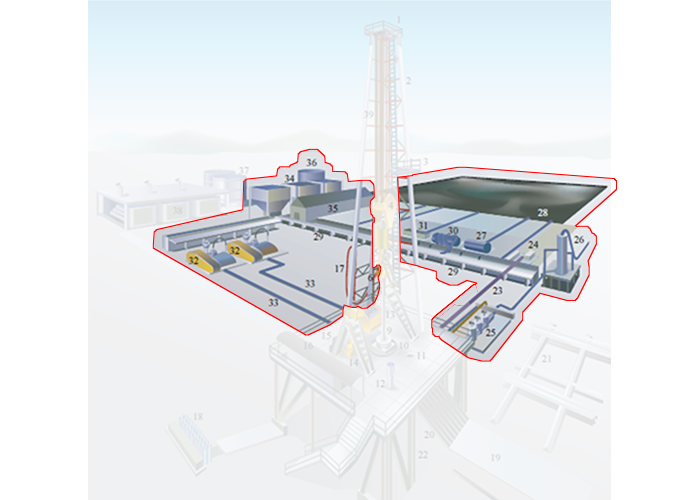
In the detailed rig schematic (Figure 9.02c), the circulation system is comprised of:
- the Swivel (Item 6)
- the Rotary Hose (Item 17)
- the Mud Return Line (Item 23)
- the Shale Shaker (Item 24)
- the Choke Manifold (Item 25)
- the Mud Gas Separator (Item 26)
- the Degasser (Item 27)
- the Reserve Pit (Item 28)
- the Mud Pits (Item 29)
- the Desander (Item 30)
- the Desilter (Item 31)
- the Mud Pumps (Item 32)
- the Mud Discharge Line (Item 33)
- the Bulk Mud Components Storage (Item 34)
- the Mud House (Item 35)
- the Water Tank (Item 36)
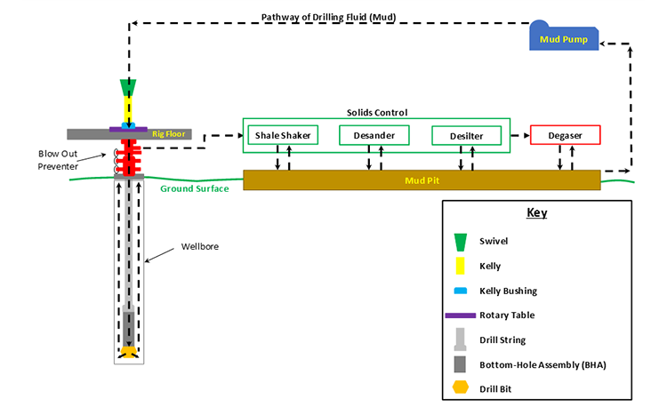
Drilling fluid is mixed in the mud pits and pumped by the mud pumps through the swivel, through the blow out preventer (not part of the circulation system) down the hollow drill pipe, through holes (Jet Nozzles) in the bit, up the annular space between drill pipe and wellbore (where it lifts the rock cuttings), to the surface, through the Solids Control Equipment (Shale Shaker, Desander, and Desilter), and back to the mud pits. A schematic of the circulation system is shown in Figure 9.05.
In this figure, fresh water-based drilling fluid (mud) is mixed with water from the Water Tank (not shown in Figure 9.05) and components from the Bulk Mud Components Storage (not shown in Figure 9.05) in the Mud Pit. The Mud Pumps then pump the mud through the swivel, kelly, kelly bushing, and rotary table down to the drill string.
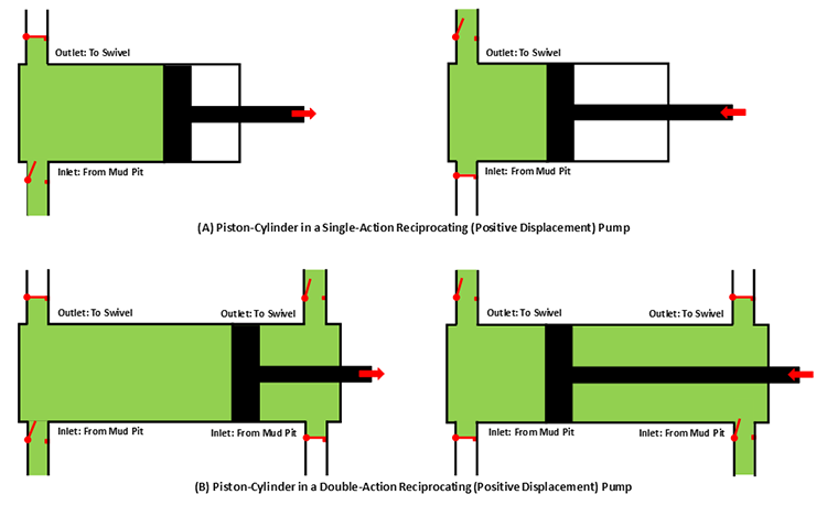
The mud pumps on a typical drilling rig are either single-action or double-action Reciprocating (Positive Displacement) Pumps which may contain two pistons-cylinders (duplex pump) or three pistons-cylinders (triplex pump). Figure 9.06 shows schematics of a single piston-cylinder in (A) a single-action and (B) a double-action reciprocating pump.
In these pumps, the positive pressure and negative pressure (suction) in the cylinder cause the valves to open and close (note: the valves in the schematic are simple representations of the actual valves). Due to the high viscosity of the drilling fluid, the inlet side of the pump may require a Charge Pump to keep fluids moving into the cylinders at high pressures and to prevent Cavitation in the pump.
From the mud pumps, the drilling fluid goes to the swivel, through the blow out preventer, and down the hollow drill string and bottom-hole assembly. The drilling fluid then goes through jet nozzles in the drill bit; at which point, it begins its return to the surface. The drilling fluid travels up the annular space between the drill pipe and the wellbore, picking up and carrying the drill cuttings up the hole.
Once the drilling fluid reaches the surface, it goes through the mud return line to the gas-mud separator and the solids control equipment. The shale shaker is where the large cuttings from the returning drilling fluid are removed. The shale shaker is a set of vibrating mesh screens that allow the mud to pass through while filtering out cuttings of different size at screen screen mesh sizes. A Mudlogger or a Well-Site Geologist may be stationed at the shale shaker to analyze the cuttings to determine the lithology of the rock and the depth within the Stratigraphic Column at which the well is currently being drilled.
The drilling fluid then passes through the Desander and Desilter. These are hydrocyclones which use centrifugal forces to separate the smaller solids from the drilling fluid. The desander typically removes solids with a diameter in the range of 45 – 74 μm, while the desilter removes solids with a diameter in the range of 15 – 44 μm.
The drilling fluid is then sent through a degasser to remove any gas bubbles that have been picked up during the circulation. These gasses may include natural gas from the subsurface or air acquired during the solids control. Typically, the degasser is a piece of equipment that subjects the drilling fluid to slight vacuum to cause the gas to expand for extraction. The drilling fluid is then returned to the mud pit to start the circulation process over again.
We have discussed the mechanics of how the drilling fluid is circulated during the drilling process, but we have not discussed the role of the drilling fluid. The term “mud” is often used in oil and gas well drilling because historically the most common water-based drilling fluids were mixtures of water and finely ground, bentonite clays which, in fact, are muds.
There are many objectives for using a drilling fluid. These include:
- lift drill cuttings from the bottom of the wellbore to the surface;
- suspend cuttings to prevent them from falling downhole if circulation is temporarily ceased;
- release the cuttings when they are brought to the surface;
- stabilize the borehole during drilling operations (exert hydrostatic or hydrodynamic pressure on the borehole to prevent rock caving into the wellbore);
- control formation pore pressures to assure desired well control (apply hydrostatic and hydrodynamic pressures in excess of the formation pore pressures to prevent fluids from entering the wellbore);
- deposit an impermeable filter cake onto the wellbore walls to further prevent fluids from permeable formations from entering the wellbore;
- minimize reservoir damage (assure low skin values) when drilling through the reservoir section of the well;
- cool the drill bit during drilling operations;
- lubricate the drill bit during drilling operations;
- allow for pressure signals from Logging While Drilling (LWD) or Measurement While Drilling (MWD) tools to be transmitted to the surface (LWD and MWD data are transmitted to the surface using pressure pulses in the drilling fluid);
- allow for pressure signals to be sent to the bottom of the well to pressure actuate certain downhole equipment;
- minimize environmental impact on subsurface natural aquifers.
As I stated earlier, historically drilling fluids were mixtures of bentonite clay, water, and certain additives to manipulate the properties of the mud (density, viscosity, fluid loss properties, gelling qualities, etc.). Today, there are several different options available for drilling fluids. These include:
- water-based muds (WBM)
- oil-based muds (OBM)
- foams
- air
Of the listed drilling fluids, the water-based muds and the oil-based muds are the most common; foam drilling and air drilling can only be used under specialized conditions. Of the two liquid based mud systems (water-based muds and oil-based muds), water-based muds are the most common mud system. They are more environmentally friendly and are used almost exclusively to drill the shallow portions of the well where fresh water aquifers exist to minimize any contamination to those aquifers. As this implies, drilling fluids can be – and often are – switched during the course of drilling operations in single well.
In addition, water-based muds are cheaper than oil-based muds, so they are used to reduce drilling costs and commonly represent the “default” selection for a drilling fluid. In other words, water-based muds are often used unless there is a specific reason to switch to an oil-based mud.
Oil-based muds are formulated with diesel oil, mineral oil, or synthetic oils as a continuous phase and water as a dispersed phase in an emulsion. In addition, additives such as emulsifiers and gelling agents are also used. They were specifically developed to address certain drilling problems encountered with water-based muds. The reasons for using an oil-based mud include:
- drilling through shales that are susceptible to swelling (in particular, highly smectite-rich shales). Shales contain a large amount of clay material and when these clays come in contact with the water in a water-based mud system, the clays may swell causing the shales to collapse into the hole. Smectite-rich shale formations are often referred to as “Gumbo” or “Gumbo Clays” in the drilling industry;
- reducing torque and drag problems in deviated wells. Since oil, a lubricant, is the continuous phase in the mud system, the torque and drag between the drill pipe and the wellbore is reduced with oil-based muds;
- achieving greater thermal stability at greater depths. Oil-based muds have been found to retain their stability (retain their desired properties) at greater down hole temperatures;
- achieving greater resistance to chemical contamination. Many substances found down-hole (salt, CO2, H2S, etc.) are soluble in water. The introduction of these substances into the water-based mud system may have a deleterious impact on different mud properties (density, viscosity, fluid loss properties, gelling properties, etc.). These substances are not soluble in oil and, therefore, have will not impact oil-based mud properties.
The first three bullet points in this list are becoming more common problems in the oil and gas industry. The shale boom in the U.S. has made long horizontal sections in shale reservoirs targets for drilling. In addition, deviated wells and deeper wells are also becoming more common. For these reasons, the use of oil-based muds is also becoming more common.
There are also several disadvantages with oil-based muds. These include:
- high initial costs. Often in an active drilling campaign, if certain depth intervals require an oil-based mud, the mud is stored and reused in different wells;
- slow rates of penetration. Historically, the rate of penetration has been statistically slower for oil-based muds than it is for water-based muds. The rate of penetration is the speed at which the drilling process progresses (depth versus time) and is a function of many factors other than mud type, including: weight on bit, RPM, lithologies being drilled through, bit type, bit wear, etc.;
- environmental concerns:
- oil contamination of subsurface fresh water aquifers,
- cleaning and disposal of oil contaminated rock cuttings;
- kick detection. If gas enters the wellbore (a Kick), it may go into solution in the oil in deeper, higher pressure sections of the well and come out of solution closer to the surface;
- formation evaluation. Some readings from well logs or core analysis may be sensitive to oil entering the formation of interest (for example, if oil from the oil-based mud enters the reservoir in the near-well vicinity, then tools used to detect oil saturation may read artificially high).
Other drilling fluids currently in use that were listed earlier are foams and air. In the context of drilling fluids, foams have the consistency of shaving cream. Both foam and air drilling are used in hard rock regions, such as in the Rocky Mountains, where drill bits render the drill cuttings to dust. Thus, the foam or air only needs to lift this dust to the surface. Air drilling is always an environmentally friendly option if it is applicable because environmental contamination by air is never an issue.