The Well Control System or the Blowout Prevention System on a drilling rig is the system that prevents the uncontrolled, catastrophic release of high-pressure fluids (oil, gas, or salt water) from subsurface formations. These uncontrolled releases of formation fluids are referred to as Blowouts. Due to the explosive nature of oil and gas, any spark on the surface can result in the ignition of the fluids and an explosion on the rig. An explosive blowout and the failure of the Well Control System were the causes of the Mocondo Well disaster that killed eleven of the rig crew on the Deep Water Horizon Rig on April 20, 2010 and resulted in 35,000 to 60,000 bbl/day of crude oil to spill into the Gulf of Mexico. We will discuss this later in the lesson.
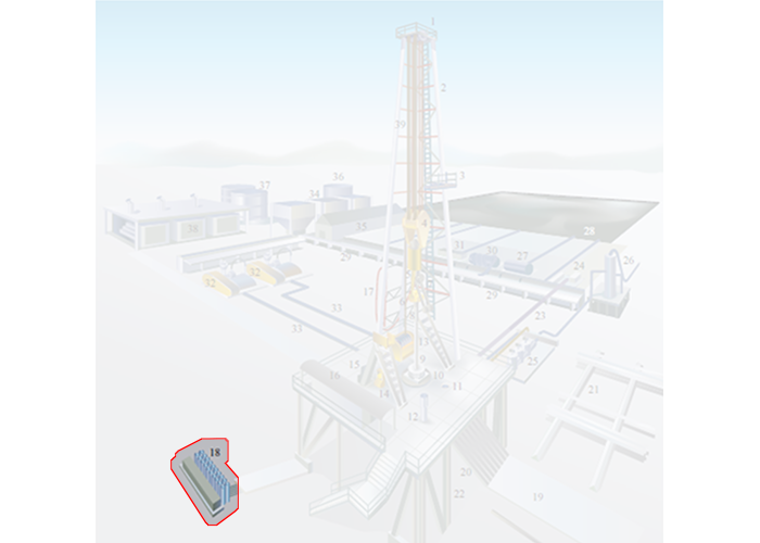
In the detailed rig schematic (Figure 9.02e), the well control system is comprised of:
- the Accumulator (Item 18)
- the Blowout Preventer (not shown in Figure 9.02e)
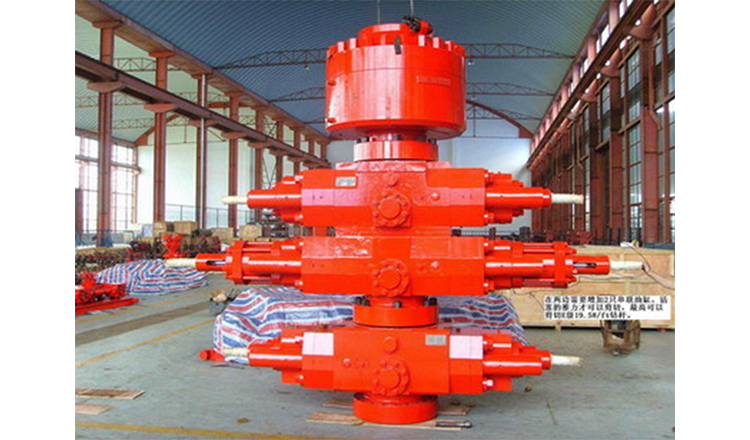
A picture of a Blowout Preventer (BOP), pronounced “B-O-P” not “bop”, is shown in Figure 9.11.
The blowout preventers are the principal piece of equipment in the well control system and are operated hydraulically; pressurized fluids are used to operate pistons and cylinders to open or close the valves on the BOP. The Accumulators (Item 18 in Figure 9.02) are used to store pressurized, non-explosive gas and pressurized hydraulic fluid to run the hydraulics systems on the rig. The accumulators store enough compressed energy to operate the blowout preventers even if the Power System of the rig is not operating.
The blowout preventer is a large system of valves each of which is capable of isolating the subsurface of the well from the rig to provide control over the well. These valves are typically stacked as shown in the Figure 9.11 and sit below the rig floor on land wells or some offshore wells; or they may sit on the seabed on other offshore wells.
A schematic diagram of a blowout preventer is shown in Figure 9.12.
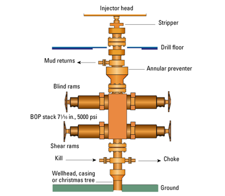
Figure 9.12 shows three type of valves (there are others) – an Annular Preventer, Blind Rams, and Shear Rams. The Annular preventer is the ring-shaped piece of equipment on the top of the BOP in Figure 9.11. As the name implies, the annular preventer is used to prevent flow through the annular space between the drill string or casing and the annular preventer. The annular preventer can also be used for non-cylindrical pipe, such as the kelly, or open hole. The annular preventer consists of a doughnut shaped bladder that when in the open position allows the drill pipe to rotate but in the closed position seals the annulus. Figure 9.13 provides a schematic of the annular preventer.
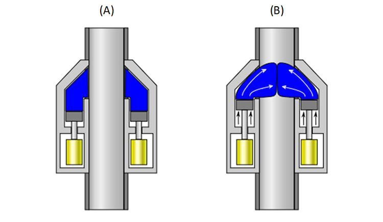
In Figure 9.13, the blue area represents the doughnut-shaped bladder. As mentioned earlier, in the open position, (A), the drill pipe can be rotated or can be run up or down; while in the closed position, (B), the bladder pushes out, closing off the drill pipe, kelly, or open hole. The bladder based sealing element is not as effective as the ram type sealing elements; however, almost all blowout preventer stacks include at least one annular preventer.
Schematics of the ram-type preventers: the blind rams, the shear rams, and the pipe rams (pipe rams are not shown in Figure 9.12) are shown in Figure 9.14.
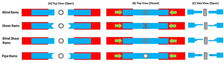
This figure shows that:
- blind rams isolate both the pipe and the annular space by crushing the pipe and it pinching-off when closed;
- shear rams isolate both the pipe and the annular space by shearing-off the pipe when closed;
- blind shear rams isolate both the pipe and the annular space by shearing-off and crushing the pipe when closed;
- pipe rams isolate the annular space by wrapping around the pipe when closed.
A blowout begins as a Kick (entry of subsurface formation fluids into the wellbore). What distinguishes a kick from a blowout is that a kick can be controlled while a blowout is uncontrollable. We have already discussed two of the defenses against kicks when we discussed drilling fluids when we listed the objectives of the drilling fluid:
- control formation pore pressures to assure desired well control (apply hydrostatic and hydrodynamic pressures in excess of the formation pore pressures to prevent fluids from entering the wellbore);
- deposit an impermeable filter cake onto the wellbore walls to further prevent fluids from permeable formations from entering the wellbore.
In the first objective re-quoted above, if we can keep the pressure exerted by the drilling mud greater than the pore pressure, then we know that fluids will flow in the direction of the mud to the formation. This cannot always be achieved. For example, if we drill through a natural fracture or if our mud density is too great and we inadvertently fracture one formation, then we may lose large quantities of the drilling fluid into the fracture (Lost Circulation). In this situation, instead of having the full weight of the mud column exerting pressure on a second (porous and permeable) formation, we may only have a fraction of the oil column height exerting a lower pressure on that second formation.
In the second objective re-quoted above, if we deposit an impermeable Drill Cake (filter cake) across an otherwise porous and permeable formation, then for a slightly Underbalanced Pressure (drilling fluid pressure lower than the formation pressure) we have created a seal between the wellbore and the formation. Again, this is not a Failsafe System because at greater underbalanced pressures, the higher formation pressures may be able to displace the drill cake.
The two previously discussed methods are used to help prevent a kick from occurring, but as mentioned they are not always successful, and kicks may still occur. The causes of a kick include:
- insufficient mud weight (density): the hydrostatic pressure exerted by the mud column is not greater than the formation pore pressure;
- improper mud replacement during tripping: while tripping out of the hole mud volumes must be pumped into the wellbore at high enough rates to replace drill pipe being removed from the wellbore;
- swabbing: removing drill pipe from the wellbore can create a negative pressure (suction) if the drill pipe is removed too quickly;
- cut mud: if gas is entering the wellbore, then it may effectively reduce the wellbore pressure gradient;
- lost circulation: as discussed earlier if large volumes of drilling fluid enter the subsurface in (1) high permeability formations, natural fractures, or drilling-induced fractures, then the effect is a shortened height and weight of the mud column.
The following are Indicators/Warning Signs of a kick:
- increase in the rate of flow of the drilling fluid returns at constant pump rates (primary indicator of a kick): The increased rate is caused by formation fluids entering the wellbore and is a strong indication of a kick. In addition, if it is a gas kick, due to the compressible nature of gas, as the gas bubble travels up-hole and hydrostatic pressures decrease, the volume of the bubble will increase due to expansion.
- volume of mud in the mud pit increases when no additional drilling fluids are added to the mud system (primary indicator of a kick): For the same reasons as mentioned above, if the volume of mud in the mud pits increases when no additional fluids have intentionally added, then the increased volume is caused by formation fluids entering the wellbore and is a strong indication of a kick.
- drilling fluids returns continue to flow when the mud pumps are turned off (primary indicator of a kick): Drilling fluid returns when the mud pumps are shut-off indicate that formation fluids are entering the wellbore and displacing the mud.
- improper wellbore fill-up/volume-balance on trips (primary indicator of a kick): If the drill pipe is removed from the wellbore, then the change in volume in the mud pits should equal the volume of the drill pipe removed from the hole. An improper volume balance is a strong indicator of a kick.
- pump pressure decrease and pump stroke increase (secondary indicator of a kick): If low density fluids are displacing heavier drilling fluid in the annulus, then this will cause the pump pressure to decrease (the annular side of the u-tube is lighter than the drill pipe side of the u-tube which contains the mud pump pressure gauge). The imbalance in the u-tube, just described, will cause the heavier drilling fluid in the drill pipe to fall due to gravity, causing the mud pump to increase the number of strokes to keep up with the pressure imbalance.
- change in the apparent weight-on-bit (secondary indicator of a kick): If the weight-on-bit indicator in the rig’s Dog House shows a change in the weight-on-bit that is not explainable by the current drilling operations, then this may be an indication of a kick. The apparent weight-on-bit is affected by the buoyance caused by the wellbore fluid, which in turn, is affected by the density of the wellbore fluid. If a lighter formation fluid begins to replace the heavier, more dense drilling fluid, then an apparent increase in the weight-on-bit will occur.
- occurrence of a Drill Break or Bit Drop (secondary indicator of a kick): A Drill Break (sudden change in the rate-of-penetration) or Bit Drop (sudden increase in the drill bit depth) typically occur at a change in the lithology of the formation being drilled. In particular, a large bit drop may be an indication of drilling through a natural facture system. Both drill breaks and bit drops are normally recorded in the drilling records. When working on naturally fracture reservoirs, these drilling records may be useful for mapping natural fractures. I personally worked in a field where we had a 12 meter (~ 36 ft) bit drop in one well in the reservoir – think about it, you are drilling away at a certain rate-of-penetration and, all of a sudden, the bit drops 36 feet for no apparent reason. This was caused by drilling through a solution enhanced fracture which over geologic time formed a cavern in the reservoir (this occurred several years prior to my arrival, but it was in the drilling records).
- reduction in the mud weight (secondary indicator of a kick): The Mud Man may observe a reduction or Cut in the mud density at the rig-site mud laboratory. This again may be an indication of a kick.
When a kick occurs, the Operating Company and Drilling Company always have well-specific plans in-place for all wells to ensure that any controllable kick does not turn into an uncontrollable blowout. I cannot go into the details of a well-specific procedures, but they will include some of the following features if a kick occurs during drilling operations:
- Stop drill pipe rotation.
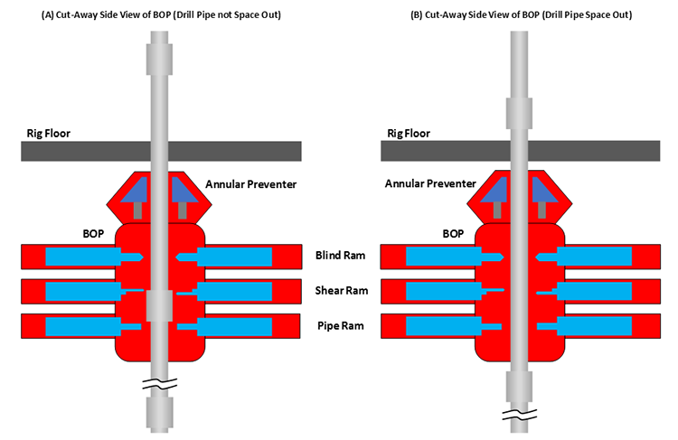
- Pick the drill bit off-bottom and Space Out (Spacing out refers to pulling the drill pipe out the hole so that the top connection – the thickest part of the drill string containing the threads and joints – is several feet above the rig floor. Spacing out ensures that the smaller diameter section of the drill string is inside the BOP, so that pipe rams can close and seat properly or blind rams or shear rams are opposite the smallest diameter section of steel. See Figure 9.15B)
- Stop the mud pumps and check for continued Mud Returns (flow of mud from the well).
- If mud returns continue:
- Shut-in the well with the annular preventer or pipe rams:
- Hard shut-in (choke in Figure 9.12 is closed)
- Soft shut-in (choke in Figure 9.12 is opened)
- If a hard shut-in was used, open the choke
- Weight Up (add the mud weighting additives) to the desired density – this is the Kill Fluid used to Kill the Well
- Circulate the kill fluid through the kill line, down the wellbore, and out of the choke (see Figure 9.12) using an industry standard method:
- The Driller’s Method
- The Weight and Wait Method
- Shut-in the well with the annular preventer or pipe rams:
Other procedures will be used if the kick occurs while tripping into or out of the well. The details of some aspects of this procedure such as hard or soft shut-ins and the circulation methods, The Driller’s Method and The Weight and Wait Method, will be discussed in detail in your later drilling classes. More importantly, for every well that you are involved with, there will always be Daily Safety Meetings that discuss the current status of the well and the important safety aspects of all drilling activities related to that day’s operations.
So, we have discussed the role of drilling fluid to exert pressure on porous and permeable formations and to coat them with an impermeable filter cake to help prevent kicks from occurring. We have also discussed the role of the blowout preventer and company procedures to control a kick once one occurs. So, how do blowouts happen?
Perhaps you remember the Macondo Blowout (Deep Water Horizon Rig) disaster. The name Macondo was the Prospect name (remember, we discussed prospects and well proposals in a previous lesson) while the Deep Water Horizon was the name of the rig. This was the largest oil spill in the Gulf of Mexico. When the disaster occurred, eleven members of the rig crew were killed by the explosion when the natural gas ignited.
The following YouTube video, "Deepwater Horizon Blowout Animation" (11:22), describes the Deep Water Horizon disaster and what its root causes were:
After learning about offshore drilling rigs, drilling crews, components of the drilling rig, kicks, and blowouts, I would highly recommend watching the movie “Deep Water Horizon” and use your knowledge about oil and gas well drilling to identify some of the technical aspects of the film. Ask yourselves some technical questions:
- What type of offshore drilling rig was the Deep Water Horizon?
- What type of well was being drilled (exploration, appraisal/delineation, or development well)?
- What part of the rig crew were the main characters (both the “good guys” and the “bad guys”)?
- What companies (operating companies, drilling companies, or service companies) did these characters work for?
- What were the root causes of the disaster?
- Why were running Cement Bond Logs (CBL) – well logs showing the quality of the cement job –and pressure-testing the cement so important to averting this disaster?
- What is “real” and what is “Hollywood”?