As stated earlier, the flow of oil to a production well is governed by Darcy’s Law. In this section, well damage is defined as a near-well permeability reduction (non-geological) caused by drilling or production. We will start our discussion by assuming that steady-state conditions prevail for the system. While steady-state conditions seldom occur in actual reservoirs, the analysis of production wells under these conditions forms the basis of the analysis methods of wells under more common reservoir conditions (pseudo steady-state conditions or transient, time-dependent conditions).
For steady-state analysis, we need to make the following assumptions:
- Flow is steady-state and Darcy’s Law applies and all of the inherent assumptions of Darcy’s Law are valid in the system.
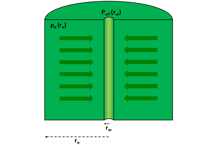
- The drainage volume is radial-cylindrical (see Figure 4.01).
- The drainage volume is bounded in the interior with a cylindrical well (radius equal to ) and kept at flowing well pressure of
- The drainage volume is bounded on the exterior with a cylindrical boundary (radius equal to ) which has an external pressure of ( < )
- The drainage volume is bounded on the top and bottom (constant height) no-flow boundaries.
- Within the drainage volume the rock properties are homogeneous (uniform with location).
- Within the drainage volume the rock properties are isotropic (uniform in all directions).
- Flow is horizontal.
With these assumptions, we can use the single-phase version of Darcy’s Law:
Now, for radial flow, we have:
Substituting into Darcy’s Law, we have:
The purpose of the negative sign in Equation 4.07 now becomes apparent: for a positive pressure gradient (pressure increasing with radius), flow is in the negative r-direction (flow is inward to the well: note direction of radii in Figure 4.01). Separating variables and integrating results in:
Now, using the assumption of a homogeneous permeability (constant with respect to location) and slightly compressible fluid (approximately constant , , and ), we have:
Performing the integration results in Equation 4.12 results in:
or,
Rearranging Equation 4.14 results in:
Equation 4.15 describes the steady-state flow of a single-phase, incompressible or slightly compressible fluid to a well in a radial-cylindrical drainage volume.