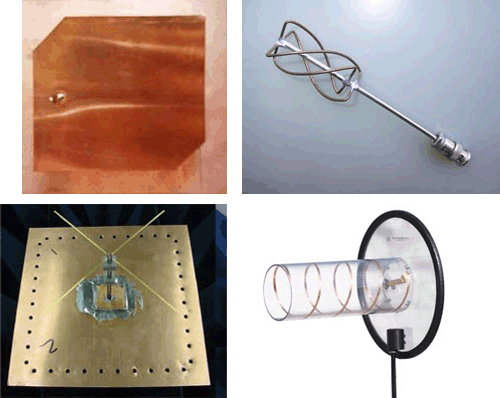
Bottom left: Dipole antenna, Bottom right: Helix antenna
Top right: LEA
Bottom left: http://www.sciperio.com/antenna/antenna-design.asp
Bottom right: www.professionalwireless.com/helical/index.aspx
The illustration shows antenna types. They are not specifically GPS antennas.
Most receivers have an antenna built in, but many can accommodate a separate tripod-mounted or range pole-mounted antenna as well. These separate antennas sometimes require connecting coaxial cables. The cables are an important detail. The longer the cable, the more of the GPS signal is lost traveling through it. They are usually in standard lengths to make sure that the impedance of the trip through the cable can be calibrated.
As mentioned earlier, the wavelengths of the GPS carriers are 19 cm (L1), 24 cm (L2) and 25 cm (L5), and antennas that are a quarter or half wavelength tend to be the most practical and efficient, so GPS antenna elements can be as small as 4 or 5 cm. Most of the receiver manufacturers use a microstrip antenna. These are also known as patch antennas. The microstrip may have a patch for each frequency, so it can receive one or all of the GPS carriers. Microstrip antennas are durable, compact, have a simple construction and a low profile. The next most commonly used antenna is known as a dipole. You may recall that this is the kind of antenna that was used with the Macrometer, the first commercial GPS receiver. A dipole antenna has a stable phase center and simple construction, but needs a good ground plane. A ground plane also facilitates the use of a microstrip antenna where it not only ameliorates multipath, but also tends to increase the antenna’s zenith gain-- in other words, the gain of the antenna straight up. A quadrifilar antenna is a single frequency antenna that has two orthogonal bifilar helical loops on a common axis. Quadrifilar antennas perform better than a microstrip on crafts that pitch and roll, like boats and airplanes. They are also used in many recreational handheld GPS receivers. Such antennas have a good gain pattern, do not require a ground plane, but are not azimuthally symmetric. The least common design is the helix antenna. A helix is a dual frequency antenna. It has a good gain pattern, but a high profile.
Bandwidth
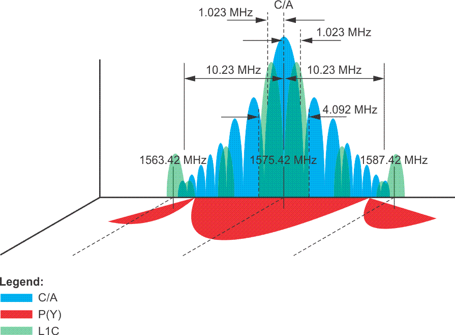
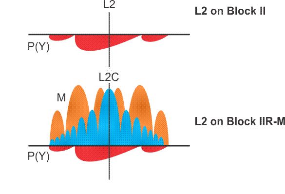
An antenna ought to have a bandwidth commensurate with its application. In general, the larger the bandwidth, the better the performance; however, there is downside. Increased bandwidth degrades the signal-to-noise ratio by including more interference. These PSD diagrams illustrate the C/A and P code signals power per bandwidth in Watts per Hertz as a function of frequency. GPS microstrip antennas usually operate in a range from about 2 to 20 MHz, which corresponds with the null-to-null bandwidth of the GPS signals. For example, the L2C signal, like the C/A, has the span of 2.046 megahertz. You can see it in the highest portion or the central lobe of the diagram. L5, like the P code, has a bandwidth of 20.46 megahertz, as you see in red. So an antenna on the front end of the receiver has to be able to accommodate that bandwidth of 20.46 megahertz if it is to track all of these signals. If the system's tracking C/A code or the L2C only, it could have a narrower bandwidth. It would need 2.046 MHz for the central lobe of the C/A code, or if it were designed to track the L1C signal, its bandwidth would need to be 4.092 MHz. A dual frequency microstrip antenna would likely operate in a bandwidth from 10 to 20 MHz.
Nearly Hemispheric Coverage
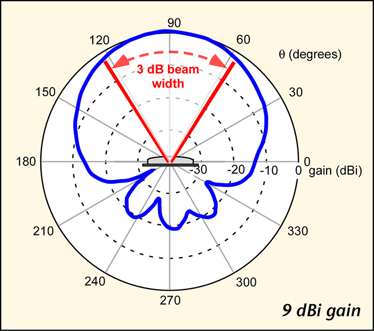
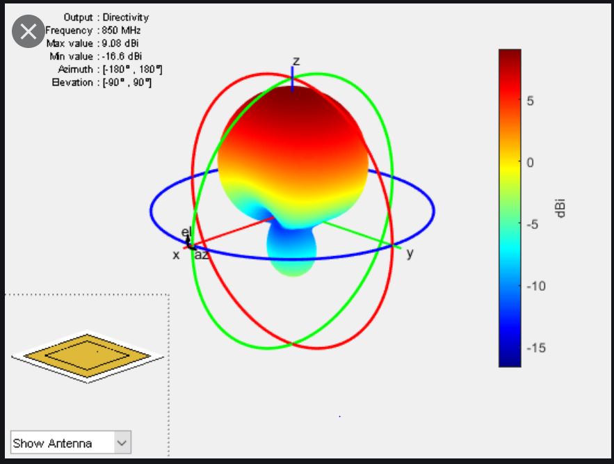
Since a GPS antenna is designed to be omnidirectional, its gain pattern, that is the change in gain over a range of azimuths and elevations, ought to be nearly a full hemisphere, but not perfectly hemispheric. For example, most surveying applications filter the signals from very low elevations to reduce the effects of multipath and atmospheric delays. A portion of the GPS signal may come into the antenna from below the mask angle; therefore, the antenna’s gain pattern is specifically designed to reject such signals. Second, the contours of equal phase around the antenna’s electronic center, that is, the phase center, are not themselves perfectly spherical.
The gain, or gain pattern, describes the success of a GPS antenna in collecting more energy from above the mask angle, and less from below the mask angle. A gain of about 3 to 5 decibels (dB) is typical for a GPS antenna. Just a brief description of a decibel-- we'll be seeing a little bit more of it. The decibel is a tenth of a bell, which was named for Alexander Graham Bell. It is a logarithmic dimensionless unit used to make a comparison. In this case, the gain of a real GPS antenna is compared to a theoretical lossless antenna that has perfectly equal capabilities in all directions. This imaginary perfection is known as an isotropic antenna. By the way a 3 decibel increase indicates a doubling of signal strength, and a 3 decibel decrease indicates a halving of signal strength so a typical omnidirectional GPS antenna with a gain of about 3 dB (decibels) has about 50% of the capability of that perfect isotropic antenna.
A decibel watt, dbW, indicates the actual power of a signal compared to a reference of one watt, The minimum power received from the C/A code on L1 is about -160dBW, -160 decibel Watts and the minimum power received from the P code on L2 is even less at -166 dBW. It is important that the GPS receiver antennas and pre-amplifiers be as efficient as possible, because the power received from the GPS satellites is low.
Antenna Orientation
In a perfect GPS antenna, the phase center of the gain pattern would be exactly coincident with its actual, physical, center. If such a thing were possible, the centering of the antenna over a point on the earth would ensure its electronic centering as well. But that absolute certainty remains elusive for several reasons.
It is important to remember that the position at each end of a GPS baseline is the position of the phase center of the antenna at each end, not their physical centers, and the phase center is not an immovable point. The location of the phase center actually changes slightly with the satellite’s signal. For example, it is different for the L2 than for L1 or L5. In addition, as the azimuth, intensity, and elevation of the received signal changes, so does the difference between the phase center and the physical center. Small azimuthal effects can also be brought on by the local environment around the antenna. But most phase center variation is attributable to changes in satellite elevation. In the end, the physical center and the phase center of an antenna may be as much as a couple of centimeters from one another. On the other hand, with today’s patch antennas, it can be as little as a few millimeters. It is fortunate that the shifts are systematic. To compensate for some of this offset error, most receiver manufacturers recommend users make sure their antennas are all oriented in the same direction when making simultaneous observations on a network of points. Several manufacturers provide reference marks on the antenna, so that each one may be rotated to the same azimuth, usually north, to maintain the same relative position between their physical and phase, electronic, centers. By orienting all the antennas in the same direction, the offset between the phase center and the physical center is in the same direction at each point. Therefore, the baselines come out exactly as if the physical and the phase center were coincident.
It's only when we're talking about control work, work that needs to be quite accurate, that all of the antennas need to be oriented to the same direction.
Height of Instrument
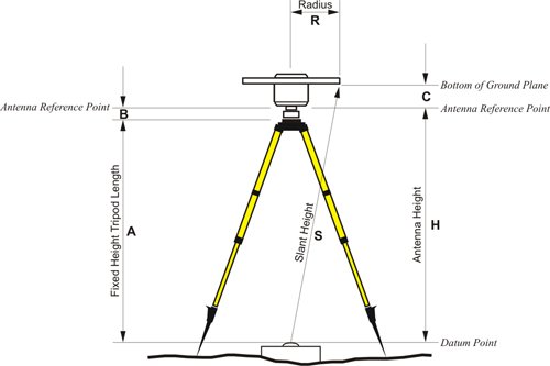
The antenna's configuration also affects another measurement critical to successful GPS work - the height of the instrument. An incorrect height of instrument is one of the most easily avoided errors. The measurement is normally made to some reference mark on the antenna. In this diagram, you see many ways of measuring that height. It can be measured at slant height or measured with a tape, usually to the antenna reference point. The ARP, or the antenna reference point, is frequently the bottom of the mount of the antenna. There's usually a correction to be added to actually bring that measurement up to the phase center of the antenna. This also becomes part of the necessary information when one is using continuously operating reference stations. We talked earlier about the fact that it is possible to take the downloads from NGS managed Continuously Operating Reference Station (CORS) stations that are available on the Internet and post-process the observations taken with a roving GPS receiver. If you are doing so, it is also necessary to know the height of the antenna at the CORS. Of course, that is not an antenna that you would've set up, but that information is available along with the files from the base station.