There are code tracking loops, the delay lock loops (DLL) and carrier tracking loops, and the phase locking loops (PLL) in the receiver. Typically, both the code and the carrier are being tracked in phase lock. The tracking loops connected to each of the receiver’s channels also work cooperatively with each other. As mentioned, dual frequency receivers have dedicated channels and tracking loops for each frequency.
Pseudoranging
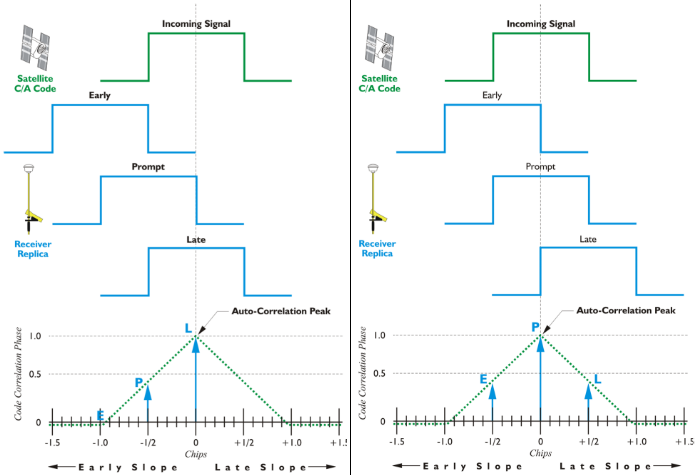
In most receivers, the first procedure in processing an incoming satellite signal is synchronization of the C/A code from the satellite’s L1 broadcast, with a replica C/A code generated by the receiver itself, i.e., the code-phase measurement. When there is no initial match between the satellite’s code and the receiver’s replica, the receiver time shifts, or slews, the code it is generating until the optimum correlation is found. Then a code tracking loop, the delay lock loop, keeps them aligned. The time shift discovered in that process is a measure of the signal’s travel time from the satellite to the phase center of the receiver’s antenna. Multiplying this time delay by the speed of light gives a range. But it is called a pseudorange in recognition of the fact that it is contaminated by the errors and biases set out in Lesson 2. The tracking loops that we see in the schematic diagram at the top are the code tracking loops.
Tracking loops are connected to each of the receiver's channels and also work cooperatively with each other. Multiple frequency receivers have dedicated channels and tracking loops for each frequency. Most receivers use the pseudorange range (the C/A code, on the L1) as the front door, so to speak, for the incoming satellite's synchronization. As we've discussed, the replica code is used to accomplish correlation. As you see in the diagram, the incoming signal is in the green at the top. The receiver replica is in blue. There is illustration of the replica as early, prompt, and late. When it is prompt, the replica and the incoming signal are correlated.
Carrier Phase Measurement
Once the receiver acquires the C/A code, it has access to the NAV message, or the newer navigation messages such as CNAV. It can read the ephemeris and the almanac information, use GPS time. But the code’s pseudoranges, alone, are not adequate for the majority of applications. Therefore, the next step in signal processing for most receivers involves the carrier phase observable. As stated earlier, just as they produce a replica of the incoming code, receivers also produce a replica of the incoming carrier wave. And the foundation of carrier phase measurement is the combination of these two frequencies. Remember, the incoming signal from the satellite is subject to an ever-changing Doppler shift, while the replica within the receiver is nominally constant.
Carrier Tracking Loop
The process begins after the PRN code has done its job and the code tracking loop is locked. By mixing the satellite’s signal with the replica carrier, this process eliminates all the phase modulations, strips the codes from the incoming carrier, and simultaneously creates two intermediate or beat-frequencies—one is the sum of the combined frequencies, and the other is the difference. The receiver selects the latter, the difference, with a bandpass filter. Then, this signal is sent on to the carrier tracking loop also known as the phase locking loop, PLL, where the voltage-controlled oscillator is continuously adjusted to follow the beat frequency exactly. This is basically how a GPS receiver locks on to that carrier and stays locked unless there is a loss of signal or a cycle slip.