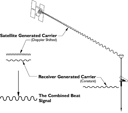
The pre-amplifier is necessary, because the signal coming in from the GPS satellite is weak. The preamplifier increases the signal’s power, but it is important that the gain in the signal coming out of the preamplifier is considerably higher than the noise. Noise is always part of the signal. Since signal processing is easier if the signals arriving from the antenna are in a common frequency band, the incoming frequency is combined with a signal at a harmonic frequency. This latter, pure sinusoidal signal is the previously mentioned reference signal generated by the receiver’s oscillator. The two frequencies are multiplied together in a device known as a mixer. Two frequencies emerge: one of them is the sum of the two that went in, and the other is the difference between them. The sum and difference frequencies then go through a bandpass filter, an electronic filter that removes the unwanted high frequencies and selects the lower of the two. It also eliminates some of the noise from the signal. For tracking the P(Y)-code, this filter will have a bandwidth of about 20 MHz, but it will be around 2 MHz if the C/A code is required. In any case, the signal that results is known as the intermediate frequency (IF), or beat frequency signal. This beat frequency is the difference between the Doppler-shifted carrier frequency that came from the satellite and the frequency generated by the receiver’s own oscillator. In fact, to make sure that it embraces the full range of the Doppler effect on the signals coming in from the GPS satellites, the bandwidth of the IF itself can vary from 5 to 10 kHz Doppler. That spread is typically lessened after tracking is achieved.
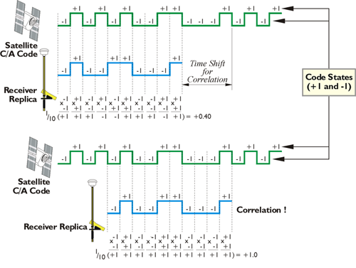
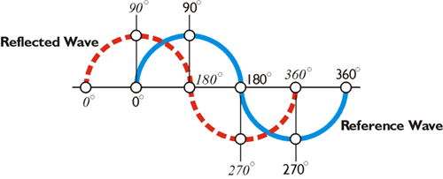
As mentioned before, a replica of the C/A or P(Y) code is generated by the receiver’s oscillator and that is correlated with the IF signal. It is at this point that the pseudorange is measured. Remember, the pseudorange is the time shift required to align the internally generated code with the IF signal, multiplied by the speed of light. The receiver also generates another replica, this time a replica of the carrier. That carrier is correlated with the IF signal and the shift in phase can be measured. The continuous phase observable, or observed cycle count, is obtained by counting the elapsed cycles since lock-on and by measuring the fractional part of the phase of the receiver generated carrier.
Channels
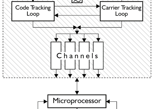
We're not talking about just receiving one signal from one satellite but rather a minimum of four, and perhaps many more, from four to more satellites and the antenna itself does not sort the information it gathers. The signals from several satellites enter the receiver simultaneously. But in the channels of the RF section, the undifferentiated signals are identified and segregated from one another. There are usually several IF stages before the copies are sent into the separate channels, each of which extract the code and carrier information from a particular satellite. A channel in a continuous tracking GPS receiver is not unlike a channel in a television set. It is hardware, or a combination of hardware and software, designed to separate one signal from all the others. A receiver may have 6 channels, 12 channels, or hundreds of channels. At any given moment, one frequency from one satellite can have its own dedicated channel, and the channels operate in parallel. This approach allows the receiver to maintain accuracy when it is on a moving platform; it provides anti-jamming capability and shortens the time to first fix (TTFF). Each channel typically operates in one of two ways; working to acquire the signal or to track it. Once the signal is acquired, it is continuously tracked unless lock is lost. If that happens, the channel goes back to acquisition mode and the process is repeated.
While a parallel receiver has dedicated separate channels to receive the signals from each satellite that it needs for a solution, a multiplexing (aka muxing) receiver gathers some data from one satellite and then switches to another satellite and gathers more data and so on. Such a receiver can usually perform this switching quickly enough that it appears to be tracking all of the satellites simultaneously. A multiplexing receiver must still dedicate one frequency from one satellite to one channel at a time; it just makes that time very short. It typically switches at a rapid pace, i.e., 50 Hz. Even though multiplexing is generally less expensive, this strategy of switching channels is now little used. There are several reasons. While a parallel receiver does not necessarily offer more accurate results, parallel receivers with dedicated channels are faster; a parallel receiver has a more certain phase lock; and there is redundancy if a channel fails and they possess a superior signal-to-noise ratio (SNR). A multiplexing receiver also has a lower resistance to jamming and interference compared to continuous tracking receivers. Whether continuous or switching channels are used, a receiver must be able to discriminate between the incoming signals. They may be differentiated by their unique C/A codes on L1, their Doppler shifts, or some other method, but, in the end, each signal is assigned to its own channel.