Phase Shift
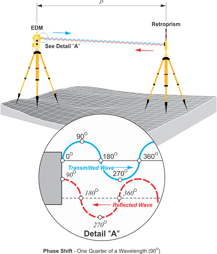
The image shows again the EDM sending out the transmitted wave in blue, with the phase angles indicated as before. The signal goes to the retro prism and returns. When it returns, shown in the dashed red line, notice the phase angles. It is clear that the return signal does not come back exactly in phase with the transmitted wave. In other words, the phase angles on the reflected wave do not match those on the transmitted wave. The key element here is that the EDM generates another wave that is exactly the same as the wave it transmitted. However, it keeps the additional wave (the blue one) at home so that when the reflected wave returns, it can be compared with it. By comparing the returned wave—the one here in the dashed red line—with the exact replica of the transmitted wave, the EDM can determine how much the returned wave is phase shifted, that is out of phase, with the original transmitted wave.
Since all measurements will not neatly fit complete wavelengths, the EDM finds the fractional part of its measurement electronically. It does a comparison. It compares the phase angle of the returning signal to that of a replica of the transmitted signal that it keeps inside to determine the phase shift. That phase shift represents the fractional part of the measurement.
How does it work? First, it is important to remember that points on a modulated carrier are defined by phase angles, such as 0°, 90°, 180°, 270° and 360°. When two modulated carrier waves reach exactly the same phase angle at exactly the same time, they are said to be in phase, coherent, or phase locked. However, when two waves reach a phase angle at different times, they are out of phase or phase shifted. For example, in the image, the sine wave shown by the dashed red line has returned to an EDM from a reflector. Compared with the sine wave shown by the solid blue line, it is out of phase by one-quarter of a wavelength. The distance between the EDM and the reflector, ρ, is then:
where:
N = the number of full wavelengths the modulated carrier has completed
d = the fractional part of a wavelength at the end that completes the doubled distance.
In this example, d is three-quarters of a wavelength because it lacks its last quarter.
Both EDM and GPS ranging use the method represented in this illustration. In GPS, the measurement of the difference in the phase of the incoming signal and the phase of the internal oscillator in the receiver reveals the small distance at the end of a range. In GPS, the process is called carrier phase ranging, as the name implies, the observable is the carrier wave itself in that case.