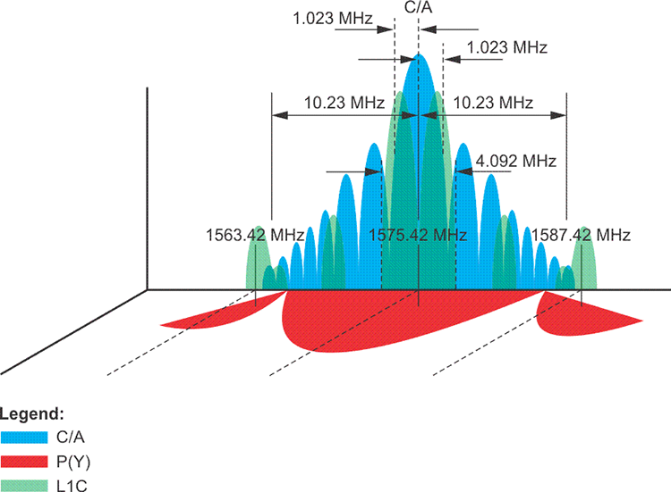
A carrier wave can be modulated in various ways. Radio stations use modulated carrier waves. The radio signals are AM, amplitude modulated or FM, frequency modulated. When your radio is tuned to 105 FM, you are not actually listening to 105 MHz; despite the announcer’s assurances, it is well above the range of human hearing. 105 MHz is just the frequency of the carrier wave that is being modulated. It is those modulations that occur that make the speech and music intelligible. They come to you at a much slower frequency than does the carrier wave. The GPS carriers L1, L2, and L5 could have been modulated in a variety of ways to carry the binary codes, the 0s and 1s, that are the codes. Neither amplitude nor frequency modulation are used in GPS. It is the alteration of the phases of the carrier waves that encodes them. It is phase modulation that allows them to carry the codes from the satellites to the receivers. One consequence of this method of modulation is that the signal can occupy a broader bandwidth than would otherwise be possible. The GPS signal is said to have a spread spectrum because of its intentionally increased bandwidth. In other words, the overall bandwidth of the GPS signal is much wider than the bandwidth of the information it is carrying. In other words, while L1 is centered on 1575.42 MHz, L2 is centered on 1227.60 MHz, and L5 on 1176.45 MHz, but the width of these signals takes up a good deal more space on each side of these frequencies than might be expected. For example, the C/A code signal is spread over a width of 2.046 MHz or so, the P(Y) code signal is spread over a width about 20.46 MHz on L1 and the coming L1C signal will be spread over 4.092 MHz as shown in the image above.
This characteristic offers several advantages. It affords better signal to noise ratio, more accurate ranging, less interference, and increased security. However, spreading the spectral density of the signal also reduces its power. The weakness of the signal makes it difficult to receive undercover.
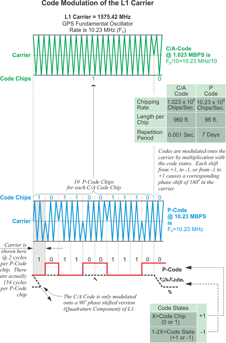
In any case, the most commonly used spread spectrum modulation technique is known as binary phase shift keying (BPSK). This is the technique used to create the NAV Message, the P(Y) code and the C/A code. The binary biphase modulation is the switching from 0 to 1 and from 1 to 0 accomplished by phase changes of 180º in the carrier wave. Put another way, at the moments when the value of the code must change from 0 to 1, or from 1 to 0, the change is accomplished by an instantaneous reverse of the phase of the carrier wave. It is flipped 180º. And each one of these flips occurs when the phase of the carrier is at the zero-crossing (the gray centerline inthe middle of the sine wave illustrations above). Each 0 and 1 of the binary code is known as a code chip. 0 represents the normal state, and 1 represents the mirror image state.
The rate of all of the components of GPS signals are multiples of the standard rate of the oscillators. The standard rate is 10.23 MHz. It is known as the fundamental clock rate and is symbolized Fo For example, the GPS carriers are 154 times Fo, or 1575.42 MHz, 120 times Fo, or 1227.60 MHZ, and 115 times Fo, or 1176.45 MHZ. These represent L1, L2, and L5 respectively. The codes are also based on Fo. 10.23 code chips of the P(Y) code, 0s or 1s, occur every microsecond. In other words, the chipping rate of the P(Y) code is 10.23 million bits per second (Mbps), exactly the same as Fo, 10.23 MHZ. The chipping rate of the C/A code is 10 times slower than the P(Y) code. It is one tenth of Fo, 1.023 Mbps. Ten P(Y) code chips occur in the time it takes to generate one C/A code chip. This is a reason why a P(Y) code derived pseudorange is more precise than a C/A code pseudorange.