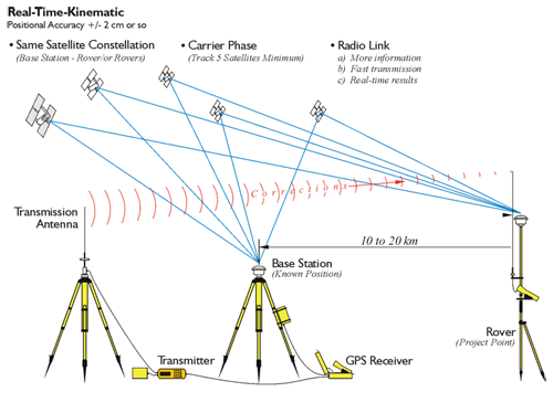
Kinematic surveying, also known as stop-and-go kinematic surveying, is not new. The original kinematic GPS/GNSS innovator, Dr. Benjamin Remondi, developed the idea in the mid-1980s. Real-Time Kinematic, RTK, is a method that provides positional accuracy nearly as good as static carrier phase positioning, but faster. RTK accomplishes positioning in real-time shown in the figure above. It involves the use of at least one stationary reference receiver, the base station, and at least one moving receiver, the rover. All the receivers involved observe the same satellites simultaneously. The base receivers are stationary on control points. The rovers move from project point to project point across, stopping momentarily at each new point, usually briefly. The collected data provides vectors between themselves and the base receivers in real-time. RTK has become routine in development and engineering surveys where the distance between the base and roving receivers can most often be measured in thousands of feet. When compared with the other relative positioning methods, there is little question that the very short sessions of the real-time kinematic method can produce the largest number of positions in the least amount of time. The remarkable thing is that this technique can do so with only slight degradation in the accuracy of the work. Real-time kinematic is done by carrier phase ranging. It must track five satellites minimum. The reason for the five satellites is basically to have one spare so that you're absolutely sure that you will have a position all the time. The base station is set up on a known point there is a transmission antenna associated with it through which a radio transmitter sends corrections to a rover. The baselines are typically at 10 to 20 kilometers, which is considerably shorter than DGPS's effective range.
Fixing the Integer Ambiguity in RTK
RTK receivers can be single- or multi-frequency receivers with GPS/GNSS antennas, but multi-frequency receivers are usual because RTK relies on carrier phase observations corrected in real-time. In other words, it depends on the fixing of the integer cycle ambiguity, and that is most efficiently accomplished with a multi-frequency GPS/GNSS receiver capable of making both carrier phase and precise pseudorange measurements. Here is one way it can be done. A search area is defined in the volume of the possible solutions, but that group is narrowed down quite a bit by using pseudoranges. If the number of integer combinations to be tested is greatly reduced with precise pseudoranges, the search can be quickly limited. The possible solutions in that volume are tested statistically, according to a minimal variance criterion, and the best one is found. This candidate is verified, that is, compared with the second best candidate. The process can take less than 10 seconds under the best circumstances where the receivers are tracking a large constellation of satellites, the PDOP is small, the receivers are multi-frequency, there is no multipath, and the receiver noise is low. This technique relies on multi-frequency information. Observations are combined into a wide lane, which has an ambiguity of about 86 cm, and the integer ambiguity is solved in a first pass. This information is used to determine the kinematic solution on L1. Therefore, it is a good idea to restrict RTK to situations where there is good correlation of atmospheric biases at both ends of the baseline. In other words, RTK is best used when the distance between the base and rover is between 10 km and 20 km, 6 miles and 12 miles, but usually less. It is fortunate that GPS/GNSS receivers with virtually instantaneous carrier phase-based positioning are available. These techniques of integer cycle ambiguity resolution, validation, and quality control are being further improved to apply to GNSS data processing.
![]()
RTK also requires a real-time wireless connection be maintained between the base station and the rover. The radio receiving antennas for the rovers will either be built into the GPS/GNSS antenna or be present as separate units. It is usual that the radio antenna for the data transmitter and the rover are omnidirectional whip antennas; however, at the base it is usually on a separate mast and has a higher gain than those at the rovers. The position of the transmitting antenna affects the performance of the system significantly. It is usually best to place the transmitter antenna as high as is practical for maximum coverage, and the longer the antenna, the better its transmission characteristics. It is also best if the base station occupies a control station that has no overhead obstructions, is unlikely to be affected by multipath, and is somewhat away from the action if the work is on a construction site. It is also best if the base station is within line of sight of the rovers. If line of sight is not practical, as little obstruction as possible along the radio link is best.
The data radio transmitter consists of an antenna, a radio modulator, and an amplifier. The modulator converts the correction data into a radio signal. The amplifier increases the signal’s power, which determines how far the information can travel. Well, not entirely; the terrain and the height of the antenna have something to do with it too. RTK work requires a great deal of information be successfully communicated from the base station to the receivers. The base station transmitter ought to be VHF, UHF, or spread spectrum-frequency hopping or direct to have sufficient capacity to handle the load. UHF spread spectrum radio modems are the most popular for DGPS and RTK applications. The typical gain on the antenna at the base is 6 dB. But while DGPS operations may need no more than 200 bits-per-second (bps), updated every 10 seconds or so, RTK requires at least 2400 bps updated about every 1/2 second or less. Like the power of the transmission, the speed of the link between the base and rover, the data rate, can be a limiting factor in RTK performance.
As mentioned earlier, RTK is at its best when the distance between the base station and the rovers is 6-12 miles or less. However, the baseline's length may be further limited by the effective range of the radio data link. In areas with high radio traffic, it can be difficult to find an open channel. It is remarkable how often the interference emanates from other surveyors in the area doing RTK as well. Most radios connected to RTK GPS/GNSS surveying equipment operate between UHF 400-475 MHz or VHF 170-220 MHz, and emergency voice communications also tend to operate in this same range, which can present problems from time to time. That is why most radio data transmitters used in RTK allow the user several frequency options within the legal range. The usual data link configuration operates at 4800 baud or faster. The units communicate with each other along a direct line-of-sight. The transmitter at the base station is usually the larger and more powerful of the two radios. However, the highest wattage radios, 35 Watts or so, cannot be legally operated in some countries. Lower power radios, from 1/2 W to 2 W, are sometimes used in such circumstances. The radio at the rover has usually lower power and is smaller. The Federal Communications Commission (FCC) is concerned with some RTK GPS/GNSS operations interfering with other radio signals, particularly voice communications. It is important for GPS/GNSS surveyors to know that voice communications have priority over data communications.
The FCC requires cooperation among licensees that share frequencies. Interference should be minimized. For example, it is wise to avoid the most typical community voice repeater frequencies. They usually occur between 455-460 MHz and 465-470 MHz. Part 90 of the Code of Federal Regulations, 47 CFR 90, contains the complete text of the FCC Rules including the requirements for licensure of radio spectrum for private land mobile use. The FCC does require application be made for licensing a radio transmitter. Fortunately, when the transmitter and rover receivers required for RTK operations are bought simultaneously, radio licensing and frequency selection are often arranged by the GPS/GNSS selling agent. Nevertheless, it is important that surveyors do not operate a transmitter without a proper license. Please remember that the FCC can levy fines for several thousand dollars for each day of illegal operation. More can be learned by consulting the FCC Wireless Fee Filing Guide. There are also other international and national bodies that govern frequencies and authorize the use of signals elsewhere in the world. In some areas, certain bands are designated for public use, and no special permission is required. For example, in Europe, it is possible to use the 2.4 GHz band for spread spectrum communication without special authorization with certain power limitations. Here in the United States, the band for spread spectrum communication is 900 MHz. It is vital, of course, that the rover and the base station are tuned to the same frequency for successful communication. The receiver also has an antenna and a demodulator. The demodulator converts the signal back to an intelligible form for the rover’s receiver. The data signal from the base station can be weakened or lost at the rover from reflection, refraction, atmospheric anomalies, or even being too close. A rover that is too close to the transmitter may be overloaded and not receive the signal properly, and, of course, even under the best circumstances, the signal will fade as the distance between the transmitter and the rover grows too large.
In RTK, generally speaking, the more satellites that are available the faster the integer ambiguities will be resolved. A multi-frequency receiver is a real benefit in doing RTK. Using a multi-frequency receiver instead of a single-frequency receiver is almost as if there were one and a half more satellites available to the observer. It is best to set up the base station over a known position first, before configuring the rover. After the tripod and tribrach are level and over the point, attach the GPS/GNSS antenna to the tribrach and, if possible, check the centering again. Set up the base station transmitter in a sheltered location at least 10 feet from the GPS/GNSS antenna, and close to the radio transmitter’s antenna. It is best if the airflow of the base station transmitter’s cooling fan is not restricted. The radio transmitting antenna is often mounted on a range pole attached to a tripod. Set the radio transmitting antenna as far as possible from obstructions and as high as stability will allow. Be certain there are no power lines in the vicinity before setting up the radio transmitting antenna to eliminate the danger of electrocution. The base station transmitter’s power is usually provided by a deep-cycle battery. Even though the attendant power cable is usually equipped with a fuse, it is best to be careful to not reverse the polarity when connecting it to the battery. It is also best to have the base station transmitter properly grounded, and avoid bending or kinking any cables. After connecting the base station receiver to the GPS/GNSS antenna, to the battery and the data collector, if necessary, carefully measure the GPS/GNSS antenna height. This measurement is often the source of avoidable error, both at the base station and the rovers. Many surveyors measure the height of the GPS/GNSS antenna to more than one place on the antenna, and it is often measured in both meters and feet for additional assurance. Select a channel on the base station transmitter that is not in use, and be sure to note the channel used so that it may be set correctly on the rovers as well. When the RTK work is done, it is best to review the collected data from the data logger. Whether or not fixed height rods have been used, it is a good idea to check the antenna heights. Incorrect antenna heights are a very common mistake. Another bulwark against blunders is the comparison of different observations of the same stations. If large discrepancies arise, there is an obvious difficulty. Along the same line, it is worthwhile to check for discrepancies in the base station coordinates. Clearly, if the base coordinate is wrong, the work created from that base is also wrong. Finally, look at the residuals of the final coordinates to be sure they are within reasonable limits. Remember that multipath and signal attenuation can pass by the observer without notice during the observations, but will likely affect the residuals of the positions where they occur.
It is certainly possible to perform a differential survey in which the position of the base station is either unknown or based on an assumed coordinate at the time of the survey. However, unless only relative coordinates are desired, the absolute position of the base station must be known or determined in the end. In other words, the base station must occupy a control position, even if that control is established later. There is an alternative to the radio link method of RTK; the corrections can be carried to the rover using a cell phone. The cell phone connection does tend to ameliorate the signal interruptions that can occur over the radio link, and it offers a somewhat wider effective range in some circumstances. The use of cell phones in this regard is also a characteristic of Real-Time Network (RTN) solutions, but connectivity is require, of course..
The Vertical Component in RTK
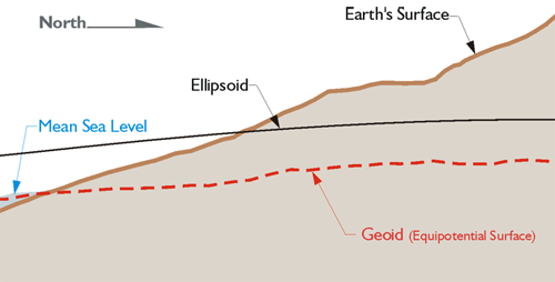
The output of RTK can appear to be somewhat similar to that of optical surveying with an electronic distance measuring (EDM) and a level. Nevertheless, it is not a good idea to consider the methods equivalent. RTK offers some advantages and some disadvantages when compared with more conventional methods. For example, RTK can be much more productive since it is available 24 hours a day and is not really affected by weather conditions. However, when it comes to the vertical component of surveying, RTK and the level are certainly not equal. GPS/GNSS can be used to measure the differences in ellipsoidal height between points with good accuracy. However, unlike a level—unaided GPS/GNSS cannot be used to measure differences in orthometric height. Orthometric elevations are not directly available from the geocentric position vectors derived from GPS/GNSS measurements. The accuracy of orthometric heights in GPS/GNSS is dependent on the veracity of the geoidal model used and the care with which it is applied. Fortunately, ever improving geoid models have been, and still are, available from NGS. Since geoidal heights can be derived from these models, and ellipsoidal heights are available from GPS/GNSS, it is certainly feasible to calculate orthometric heights, especially when a geoid model is on-board the RTK systems. However, it is important to remember that without a geoid model RTK will only provide differences in ellipsoid heights between the base station and the rovers. It is not a good idea to presume that the surface of the ellipsoid is sufficiently parallel to the surface of the geoid and ignore the deviation between the two. They may depart from one another as much as a meter, approximately 3 feet, in 4 or 5 kilometers, 2.5 to 3 miles.