As mentioned earlier, redundancy in RTK work can be achieved by occupying each newly established position twice, and it is best if the second occupation is done using a different base station than was used to control the first. If this technique is used, the control points occupied by base stations should not be too close to one another. Each time the base is set up, and before it is taken down, it is best to do a check shot on at least one known control point to verify the work. And in order to ensure that the GPS/GNSS constellation during the second occupation differs substantially from that of the first, it is best if the second occupation takes place not less than 4 hours and not more than 8 hours later than the first. Although, an interval as short as 20 minutes can have some benefit. To ensure that the centering is correct during the short occupations of RTK, it is best if a bipod is used with a fixed height rod to eliminate the possibility of incorrect height of instrument measurement corrupting the results. Concerning heights, if orthometric heights in real-time are desired, a geoidal model is required, and it is best if it is the most recent. However, please note that work retraced with a different geoidal model than was used initially will likely show vertical differences at the reoccupied points. Some rover configurations facilitate in-fill surveys. In other words, when the correction signals from the base station fail to reach the rover, the collected data is stored in the memory of the receiver for postprocessing after the work is completed.
Site Calibration
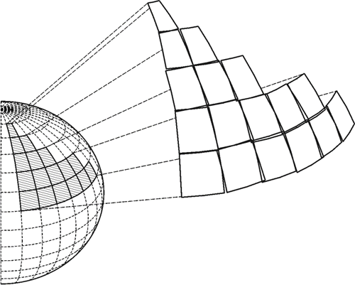
The area of interest that is the project area, covered by an RTK survey, is usually relatively small and defined. Typically, a site calibration, aka localization, is performed to prepare such a GPS/GNSS project to be done using plane coordinates. A site calibration establishes the relationship between geographical coordinates—latitude, longitude, and ellipsoidal height—with plane coordinates—northing, easting, and orthometric heights across the area. In the final analysis, the relationship is expressed in three dimensions: translation, rotation, and scale. Because of the inevitable distortion that a site calibration must model, one of the prerequisites for such localization is the enclosure of the area by the control stations that will be utilized during the work. In the horizontal plane, the method of using plane coordinates on an imaginary flat reference surface with northings and eastings, or x- and y-coordinates assumes a flat earth. That is incorrect, of course, but a viable simplification if the area is small enough and the distortion is negligible. Such local tangent planes fixed at discrete points, control points, by GPS/GNSS site calibration have been long used by land surveyors. Such systems demand little, if any, manipulation of the field observations, and once the coordinates are derived, they can be manipulated by straightforward plane trigonometry. In short, Cartesian systems are simple and convenient.
However, there are difficulties as the area grows, as was mentioned earlier. For example, typically, each of these planes has a unique local coordinate system derived from its own unique site calibration. The axes, the scale, and the rotation of each one of these individual local systems will not be the same as those elements of its neighbor’s coordinate system. Therefore, when a site calibration is done and a local flat plane coordinate system is created, it is important to keep all of the work in that system inside limits created by the control points used in its creation. In the simplest case, a single point calibration, a flat plane is brought tangent to the earth at one point, but a more typical approach is the utilization of three or four points enclosing the area of interest to be covered by the independent local coordinate system. Working outside of the limits created by those points should be avoided, as it involves working where the distortion has not been modeled. It might be said that a site calibration is a best fit of a plane onto a curved surface, in which the inevitable distortion is distributed in both the horizontal and vertical planes. The vertical aspect is particularly important. It is called upon to adjust the measured GPS/GNSS ellipsoid heights to a desired local vertical datum. Therefore, it must account for undulations in the geoid because the separation between the ellipsoid and geoidal models is seldom entirely consistent over the project area. The separation is not consistent and usually can be modeled approximately as a trend across the area of interest so that the site calibration typically produces an inclined plane in the vertical aspect. Toward that end, the set of control points used to establish the site calibration must have both geographical coordinates—latitude, longitude, and ellipsoidal height—and plane coordinates—northing, easting, and orthometric heights in the desired local system. It is best if these control points are from the National Spatial Reference System (NSRS) when possible that enclose the project and are distributed evenly around its boundary.