Image ID: 1618, NOAA's Historic Coast & Geodetic Survey (C&GS) Collection
Location: Ozark Mountains, Missouri
Photo Date: 1935
Source: http://www.photolib.noaa.gov/cgs/triangulation.html
Publication of the US Dept. of Commerce, NOAA, NOAA Central Library, COAA Privacy Policy / NOAA Desclaimer
Last Updated: April 23, 2007
Static Survey Project Design
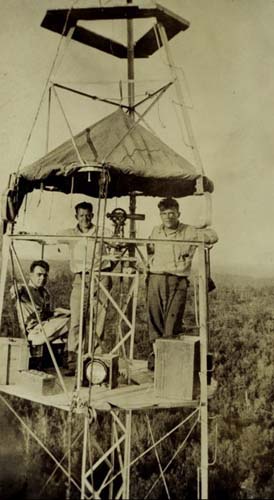
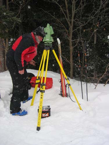
The selection of satellites to track, start and stop times, mask elevation angle, assignment of data file names, reference position, bandwidth, and sampling rate are some options useful in the static mode, as other GPS/GNSS surveying methods. These features may appear to be prosaic, but their practicality is not always obvious. For example, satellite selection can seem unnecessary when using a receiver with sufficient independent channels to track all satellites above the receiver’s horizon without difficulty. However, a good survey project design pays dividends by limiting lost time and maximizing productivity. When geodetic surveying was more dependent on optics than electronic signals from space, horizontal control stations were set with station intervisibility in mind, not ease of access. Therefore, it is not surprising that stations established in that way are frequently difficult to reach. Not only are they found on the tops of buildings and mountains, they are also in woods, beside transmission towers, near fences, and generally obstructed from GPS/GNSS signals. The geodetic surveyors that established them could hardly have foreseen a time when a clear view of the sky above their heads would be crucial to high-quality control. The illustration shows some surveyors on a Bilby tower, high above the Ozark Mountains in Missouri. Their observations were done at night with angles turned to far away lights to establish horizontal control by triangulation. It's hardly surprising that at the time surveyors were working on these towers they weren't terribly concerned with the sky visibility at the stations they occupied and set. They were concerned with getting high enough over obstructions to see the other stations.
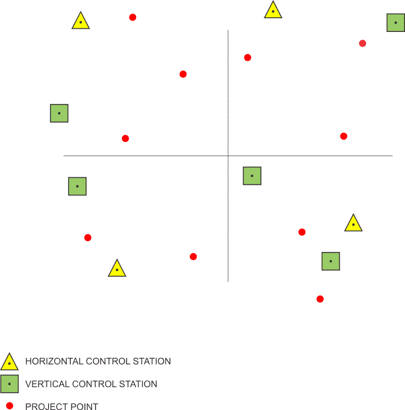
In fact, it is only recently that most private surveyors have had any routine use for NGS stations. Many station marks have not been occupied for quite a long time. Since the primary monuments are often found deteriorated, overgrown, unstable, or destroyed. The role of passive marks is changing rapidly. In any case, it is a good idea to propose reconnaissance of several more than the absolute minimum of three horizontal control stations. Fewer than three makes any check of their positions virtually impossible. Many more are usually required in a GPS/GNSS route survey. In general, in GPS/GNSS networks, the more -chosen horizontal control stations that are available, the better. Some stations will almost certainly prove unsuitable unless they have been used previously in GPS/GNSS work. The location of the stations, relative to the GPS/GNSS project itself, is also an important consideration in choosing horizontal control. For work other than route surveys, a handy rule of thumb is to divide the project into four quadrants and to choose at least one horizontal control station in each. The actual survey should have at least one horizontal control station in three of the four quadrants. Each of them ought to be as near as possible to the project boundary. Supplementary control in the interior of the network can then be used to add more stability to the network. At a minimum, route surveys require horizontal control at the beginning, the end, and the middle. Long routes should be bridged with control on both sides of the line at appropriate intervals. The standard symbol for indicating horizontal control on the project map is a triangle.
Vertical Control
Those stations with a published accuracy high enough for consideration as vertical control are symbolized by an open square or circle on the map. Those stations that are sufficient for horizontal control are symbolized as triangles. Where there is horizontal and vertical control the symbol is a combination of the triangle and square.
A minimum of four vertical control stations are needed to anchor a GPS/GNSS static network. A large project should have more. In general, the more benchmarks available the better. Vertical control is best located at the four corners of a project. Orthometric elevations are best transferred by means of classic spirit leveling; such work should be built into the project plan when it is necessary. When spirit levels are planned to provide vertical control positions, special care may be necessary to ensure that the precision of such conventional work is as consistent as possible with the rest of the survey. Route surveys require vertical control at the beginning and the end. They should be bridged with benchmarks on both sides of the line at intervals from 5 to 10 km. When the distances involved are too long for spirit leveling to be used effectively, two independent GPS/GNSS measurements may suffice to connect a benchmark to the project. However, it is important to recall the difference between the ellipsoidal heights available from a GPS/GNSS observation and the orthometric elevations yielded by a level circuit.
Plotting Project Points
A solid dot is the standard symbol used to indicate the position of project points. Some variation is used when a distinction must be drawn between those points that are in place and those that must be set.
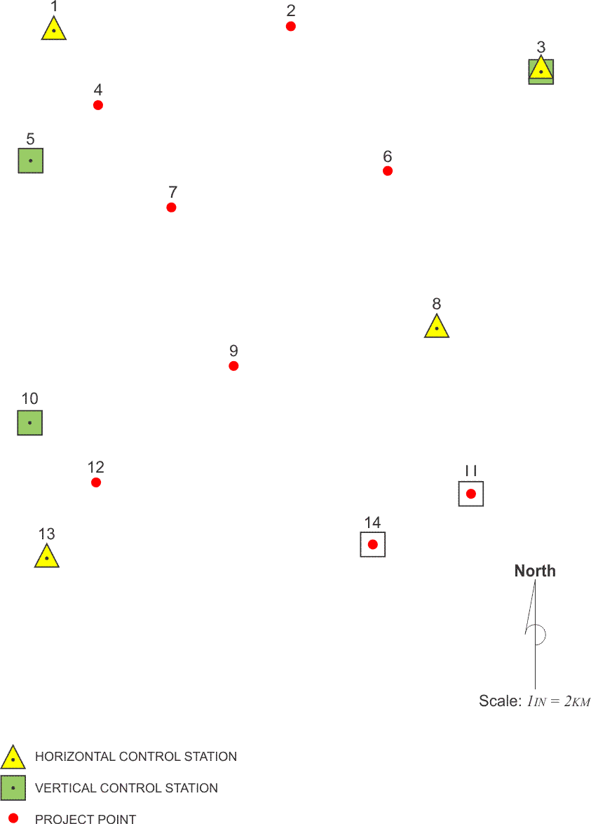
When its location is appropriate, it is always a good idea to have a vertical or horizontal control station serve double duty as a project point. While the precision of their plotting may vary, it is important that project points be located as precisely as possible even at this preliminary stage. The subsequent observation schedule will depend to some degree on the arrangement of the baselines. Also, the preliminary evaluation of access, obstructions, and other information depends on the position of the project point relative to these features. In the design, the project points are indicated. These are the points on which coordinates are going to be required based upon the control available around them.
Evaluating Access
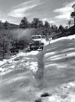
When all potential control and project positions have been plotted and given a unique identifier, some aspects of the survey can be addressed a bit more specifically. If good roads are favorably located, if open areas are indicated around the stations, and if no station falls in an area where special permission will be required for its occupation, then the preliminary plan of the survey ought to be remarkably trouble-free. However, it is likely that one or more of these conditions will not be so fortunately arranged. The speed and efficiency of transportation from station to station can be assessed to some degree from the project map. It is also wise to remember that while inclement weather does not disturb GPS/GNSS observations whatsoever, without sufficient preparation it can play havoc with surveyors’ ability to reach points over difficult roads or by aircraft. Since in a static GPS/GNSS survey, the control points and the points to be coordinated—the project points—need to be occupied simultaneously, they need to observe the same constellation of satellites at the same time. It's important to be able to be on the station ready to observe when the sessions begin, simultaneously on control and project points.
Planning Offsets
If control stations or project points are located in areas where the map indicates that topography or vegetation will obstruct the satellite’s signals, alternatives may be considered. A shift of the position of a project point into a clear area may be possible where the change does not have a significant effect on the overall network. A control station may also be the basis for a less obstructed position, transferred with a short level circuit or traverse. Of course, such a transfer requires availability of conventional surveying equipment on the project. In situations where such movement is not possible, careful consideration of the actual paths of the satellites at the station itself during on-site reconnaissance may reveal enough windows in the gaps between obstructions to collect sufficient data by strictly defining the observation sessions.
Planning Azimuth Marks
Azimuth marks are a common requirement in GPS/GNSS projects. They are an accompaniment to static GPS/GNSS stations when a client intends to use them to control subsequent conventional surveying work. Of course, the line between the station and the azimuth mark should be as long as convenience and the preservation of line-of-sight allows. It is wise to take care that short baselines do not degrade the overall integrity of the project. Occupations of the station and its azimuth mark should be simultaneous for a direct measurement of the baseline between them. Both should also be tied to the larger network as independent stations. There should be two or more occupations of each station when the distance between them is less than 2 km. An alternative approach may be to derive the azimuth between a GPS/GNSS station and its azimuth mark with an astronomic observation.

Obtaining Permissions
Another aspect of access can be considered when the project map finally shows all the pertinent points. Nothing can bring a well-planned survey to a halt faster than a locked gate, an irate landowner, or a government official that is convinced he should have been consulted previously. To the extent that it is possible from the available mapping, affected private landowners and government jurisdictions should be identified and contacted. Taking this precaution at the earliest stage of the survey planning can increase the chance that the sometimes long process of obtaining permissions, gate keys, badges, or other credentials has a better chance of completion before the survey begins.
Any aspect of a GPS/GNSS survey plan derived from examining mapping, virtual or hardcopy, must be considered preliminarily. Most features change with time, and even those that are relatively constant cannot be portrayed on a map with complete exactitude. Nevertheless, steps toward a coherent workable design can be taken using the information they provide.